


Groundsmaster 4000−D Page 5 − 29 Electrical System
Battery Service
The battery is the heart of the electrical system. With
regular and proper service, battery life can be extended.
Additionally, battery and electrical component failure
can be prevented.
CAUTION
When working with batteries, use extreme cau-
tion to avoid splashing or spilling electrolyte.
Electrolyte can destroy clothing and burn skin or
eyes. Always wear safety goggles and a face
shield when working with batteries.
Electrolyte Specific Gravity
Fully charged: 1.265 corrected to 80
o
F (26.7
o
C)
Discharged: less than 1.240
Battery Specifications
BCI Group Size 24
650 CCA at 0
o
F (−17.8
o
C)
Reserve Capacity of 110 minutes at 80
o
F (26.7
o
C)
Dimensions (including terminal posts and caps)
Length 10.2 inches (25.9 cm)
Width 6.64 inches (16.9 cm)
Height 8.99 inches (22.8 cm)
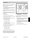
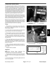
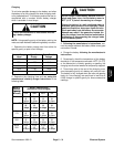
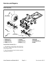
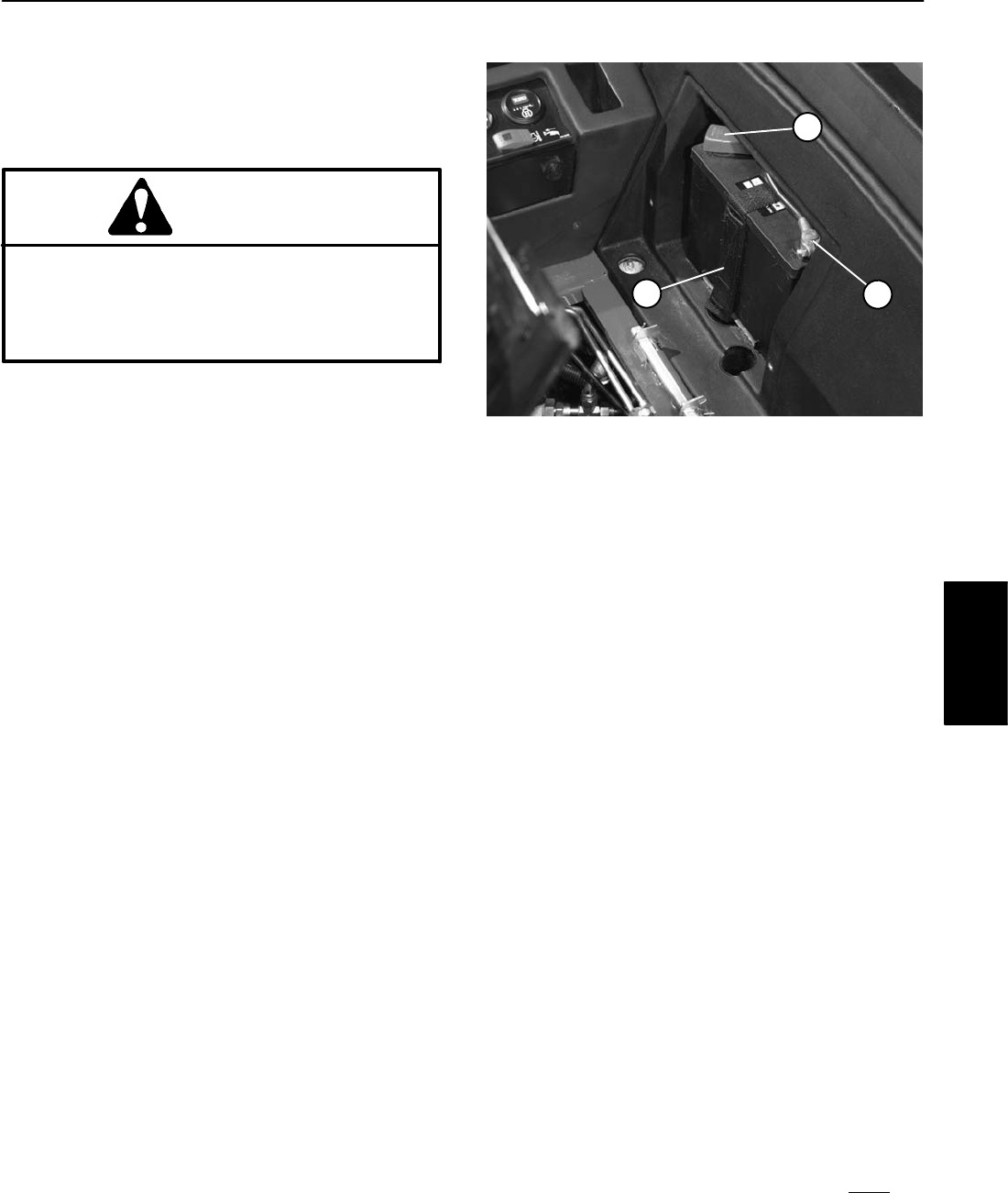
Removal and Installation (Fig. 43)
See Operator’s Manual for battery removal and installa-
tion information.
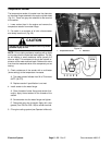
NOTE: Before connecting the negative (ground) cable,
connect a digital multimeter (set to amps) between the
negative battery post and the negative (ground) cable
connector. The reading should be less than 0.1 amp. If
the reading is 0.1 amp or more, the unit’s electrical sys-
tem should be tested and repaired.
Inspection, Maintenance, and Testing
1. Perform following inspections and maintenance:
A. Check for cracks. Replace battery if cracked or
leaking.
B. Check battery terminal posts for corrosion. Use
wire brush to clean corrosion from posts.
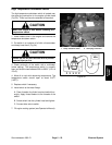
IMPORTANT: Before cleaning the battery, tape or
block vent holes to the filler caps and make sure the
caps are on tightly.
C. Check for signs of wetness or leakage on the top
of the battery which might indicate a loose or missing
filler cap, overcharging, loose terminal post, or over-
filling. Also, check battery case for dirt and oil. Clean
the battery with a solution of baking soda and water,
then rinse it with clean water.
1. Negative cable
2. Positive cable
3. Battery retainer
Figure 43
3
2
1
D. Check that the cover seal is not broken away. Re-
place the battery if the seal is broken or leaking.
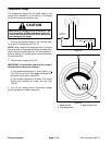
E. Check the electrolyte level in each cell. If the level
is below the tops of the plates in any cell, fill all cells
with distilled water between the minimum and maxi-
mum fill lines. Charge at 15 to 25 amps for 15 min-
utes to allow sufficient mixing of the electrolyte.
2. Conduct a hydrometer test of the battery electrolyte.
IMPORTANT: Make sure the area around the cells is
clean before opening the battery caps.
A. Measure the specific gravity of each cell with a
hydrometer. Draw electrolyte in and out of the
hydrometer barrel prior to taking a reading to warm−
up the hydrometer. At the same time take the tem-
perature of the cell.
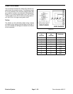
B. Temperature correct each cell reading. For each
10
o
F (5.5
o
C) above 80
o
F (26.7
o
C) add 0.004 to the
specific gravity reading. For each 10
o
F (5.5
o
C) be-
low 80
o
F (26.7
o
C) subtract 0.004 from the specific
gravity reading.
Example: Cell Temperature 100
o
F
Cell Gravity 1.245
100
o
F minus 80
o
F equals 20
o
F
(37.7
o
C minus 26.7
o
C equals 11.0
o
C)
20
o
F multiply by 0.004/10
o
F equals 0.008
(11
o
C multiply by 0.004/5.5
o
C equals 0.008)
ADD (conversion above) 0.008
Correction to 80
o
F (26.7
o
C) 1.253
Electrical
System