


Groundsmaster 4000−D Page 7 − 13 Chassis
Yoke Joint Assembly
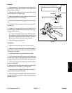
1. Apply a coating of grease to bearing bores of yoke.
2. Press one bearing partially into yoke.
3. Insert cross into yoke and bearing.
4. Hold cross in alignment and press bearing in until it
hits the yoke.
5. Install snap ring to secure installed bearing.
6. Place second bearing into yoke bore and onto cross
shaft. Press second bearing into yoke and install snap
ring.
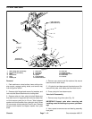
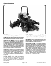
Installation
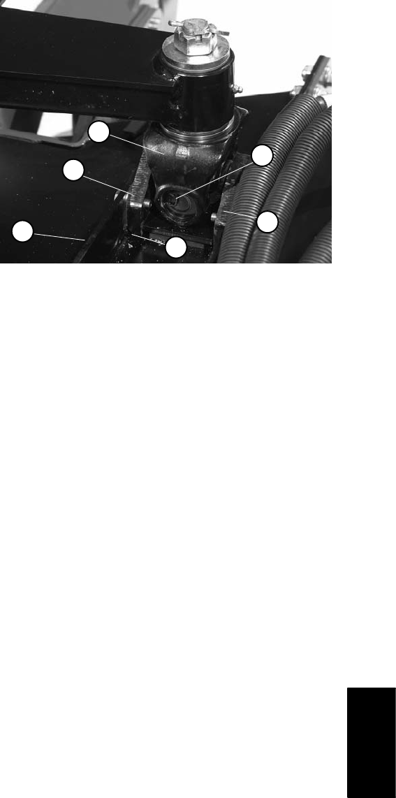
1. Press yoke joint to cutting deck base mounts with the
angled edge of the mount assembled away from the
joint (Fig. 12). The outside of the yoke bearing cup
should be flush with the mount surface.
2. Place rubber pad and plate into deck mount. Make
sure that tabs on plate and pad align with slots in base
mount.
3. Position yoke joint with base mounts to deck mounts
(Fig. 12) and install shims. Secure base mounts with cap
screws and flat washers. Torque screws from 27 to 33
ft−lb (37 to 44 N−m).
4. Place spacer washer (chamfered ID side down) and
then thrust washer onto yoke joint shaft. Insert yoke
shaft up through lift arm bushings. Place additional
thrust washer and then hardened washer on yoke shaft
and secure with slotted hex nut. Torque nut from 150 to
180 ft−lb (203 to 244 N−m) while aligning hole in shaft
with slot in nut. Install cotter pin.
5. Secure deck mount to cutting deck with eight flange
head screws, flat washers, and lock nuts.
6. Grease yoke joint and lift arm bushing after installa-
tion on machine (see Operator’s Manual).
7. After assembly is completed, raise and lower the cut-
ting deck to verify that hydraulic hoses and fittings do not
contact anything.
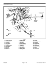
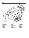
1. Joint yoke
2. Base mount
3. Angled edge of mount
4. Deck mount
5. Snap ring
Figure 12
2
1
3
4
2
5
Chassis