


Rev. E
Groundsmaster 4000--DHydraulic System (Rev. B) Page 4 -- 68
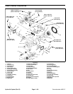
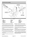
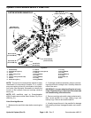
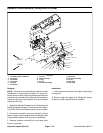
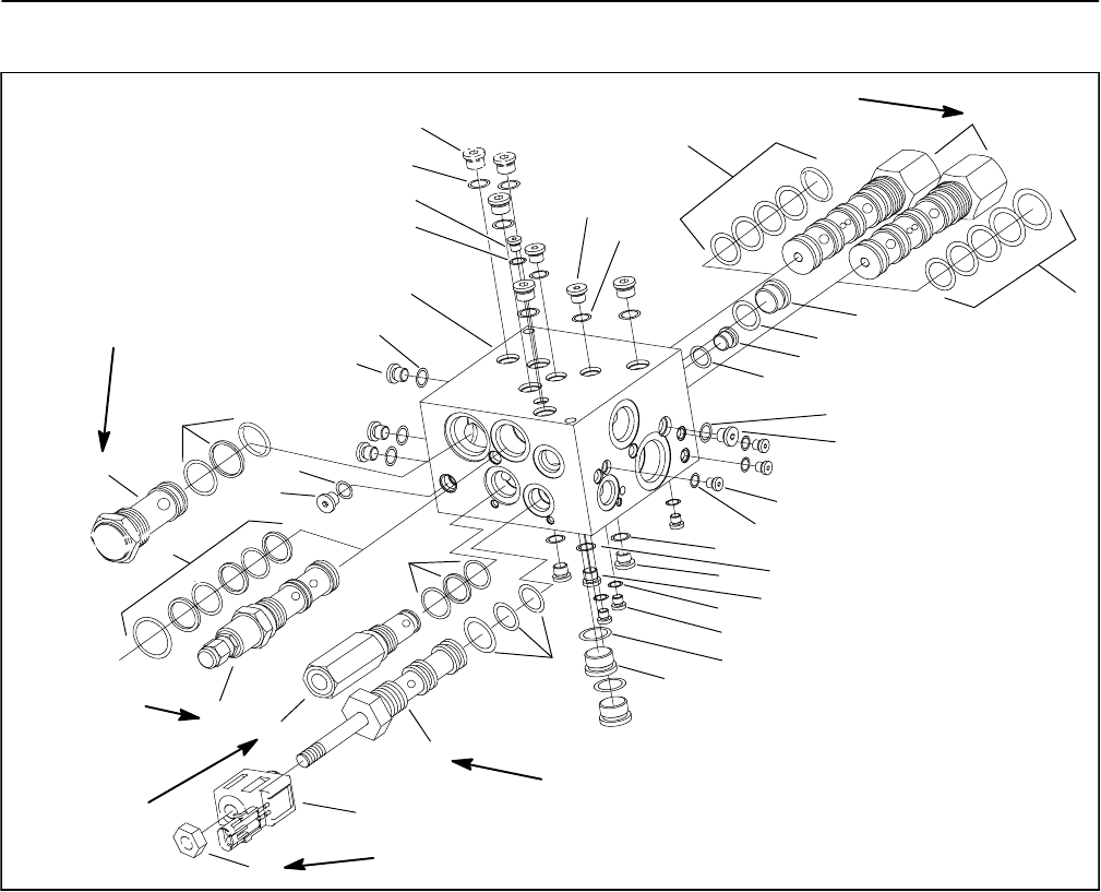
Hydraulic Control Manifold Service: 4 Wheel Drive
1. Manifold body
2. Solenoid valve (port 2)
3. Seal kit
4. Check valve (port 3)
5. Seal kit
6. Control valve (ports 5A & 5B)
7. Seal kit
8. Relief valve (port 7)
9. Seal kit
10. Reducing valve (port 8)
11. Seal kit
12. Plug (SAE #2)
13. O--ring
14. Plug (SAE #4)
15. O--ring
16. Plug (SAE #5)
17. O--ring
18. Plug (SAE #6)
19. O--ring
20. Plug (SAE #10)
21. O--ring
22. Solenoid coil
23. Nut
Figure 50
6
7
20
21
18
19
16
17
19
18
16
17
12
13
20
21
12
13
16
17
14
15
12
13
16
17
16
17
10
8
22
2
3
1
23
4
5
11
9
7
35 to 40 ft--lb
(47to54N--m)
25 to 30 ft--lb
(34to41N--m)
80 to 90 ft--lb
(108 to 122 N--m)
60 to 70 ft--lb
(81to95N--m)
4to6ft--lb
(5 to 8 N--m)
80 to 90 ft--lb
(108 to 122 N--m)
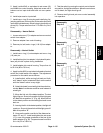
EATON/VICKERS MANIFOLD
NOTE: The ports on the manifold are marked for easy
identification of components. Example: P1 is a piston
pump connection port and 2 is the location for the sole-
noid valve (See Hydraulic Schematics to identify the
function of the hydraulic lines and cartridge valves at
each port).
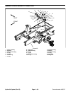
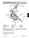
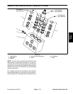
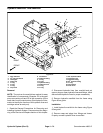
NOTE: 4WD manifolds used on Groundsmaster
4000--D machines are either Eaton/Vickers (Fig. 50) or
JEM (Fig. 51).
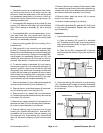
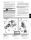
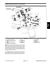
Valve Cartridge Service
1. Make sure the manifold is clean before removing the
valve.
2. If cartridge is solenoid operated, remove nut secur-
ing solenoid to the cartridge valve. Carefully slide sole-
noid off the valve.
IMPORTANT: Use care when handling the valve car-
tridge. Slight bending or distortion of the stem tube
can cause binding and malfunction.
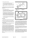
3. Remove cartridge valve with a deep socket wrench.
Note correct location for o--rings, s ealing rings, and
backup rings. Remove and discard seal kit.
4. Visually inspect the port in the manifold for damage
to the sealing surfaces, damaged threads, and contami-
nation.