


Groundsmaster 4000--DHydraulic System (Rev. B) Page 4 -- 62
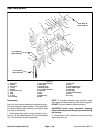
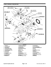
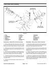
3. Inspect camplate assembly:
A. The finish on the pistonshoe surfaces ofthe cam-
plate (11) should show no signs of scoring.
B. Inspect camplate (11) bushing surface for wear.
Also inspect surface for coating transfer from bush-
ing.
4. Inspect bushing (44) for c ontamination embedment
within coating of bushing surface coming in contact with
camplate (11).
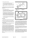
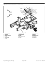
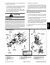
5. Inspect rotating kit (Fig. 45):
A. The pistons should move freely in the rotating kit
piston block bore. If they are sticky in the bore, ex-
amine the bore for scoring or contamination.
B. Examine the O.D. of the pistons for finish condi-
tion. They should not show wear or deep scratches.
Inspect the shoes for a snug fit on the ball end of the
pistons and a flat smooth surface that comes in con-
tact with the camplate. Do not lap piston shoes.
C. Examine the spider for wear in the pivot area.
D. Examine the spider pivot to insure smoothness
and no signs of wear.
Reassembly
1. All parts should be cleaned and internal pump parts
lubricated with clean hydraulic oil before reassembly.
2. If necessary, press new bearing into pump housing
to dimension shown in Figure 44 with the numbered end
of bearing outward.
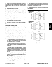
3. Install the two newseal sub--assemblies (37) intothe
servo piston cavity of pump housing (19).
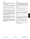
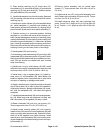
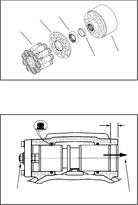
4. Screw the cover plate (10) onto the servo piston as-
sembly (7). Install new cover plate gasket (33) in place
on pump housing. Install servo piston assembly (7) and
cover plate (10) into servo piston bore in right side of
housing (Fig. 46). Retain cover plate with four washers
(31) and socket headscrews (5).Torque screwsfrom 40
to 48 in--lb (4.5 to 5.4 N--m). To obtain neutral, centering
the servo piston assembly is required. Measure in from
the left side and set servo piston .500 in. (12.7 mm) from
surface of housing servo bore as shown in Figure 46.
NOTE: Re--adjustment may be required for neutral at
unit start--up.
1. Piston assemblies
2. Spider
3. Spider pivot
4. Piston block
5. Retainer
Figure 45
1
2
3
4
5
Figure 46
.500 inch
(12.7 mm)
Left Side
Right Side
Install servo piston
Adjust to center piston
in this direction
Front flange -- Drive shaft end of pump
5. Install new sealwasher (4), washer (29),and jam nut
(1) to servo piston bolt. Holding servo piston bolt with
hex key wrench, torque jamnut from 150 to 160 in--lb (17
to 18 N--m). Check the centering of servo piston assem-
bly (7). Install new cover plate gasket (33) and cover
plate (9) to open side of servo piston and retain with four
washers (31) and socket head screws (5). Torque
screwsfrom40to48in--lb(4.5to5.4N--m).
6. Press dowel bushings (40) into cradle and secure
bushing (44) onto cradle with button head cap screw
(43). Torque button head cap screw from 14 to 16 in--lb
(1.6 to 1.8 N--m).
7. Place cradle sub--assembly (41) into housing (19)
making sure dowel bushings (40) and cradle (41) are
completely seated into housing. Retain cradle sub--as-
sembly with two cap screws (42) after applying Loctite
#277 (or equivalent) to the end of threads. Torque cap
screwsfrom25to28ft--lb(34to38N--m).