


Groundsmaster 4000--D Hydraulic System (Rev. B)Page 4 -- 31
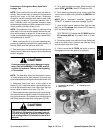
Procedure for Cutting Deck Gear Pump Flow Test
NOTE: Overa periodof time, the gearsand wear plates
in the pump can wear. A worn pump will by pass oil and
make the pump less efficient.Eventually,enough oil loss
will occur to cause the cutting unit motors to stall under
heavy cutting conditions. Continued operation with a
worn, inefficient pump can generate excessive heat and
cause damage to the s eals and other components in the
hydraulic system.
1. Make sure hydraulic oil is at normal operating tem-
perature by operating the machine for approximately 10
minutes. Make sure the hydraulic tank is full.
2. Park machine on alevel surface withthe cutting units
lowered and off. Make sure engine is off and the parking
brake is engaged.
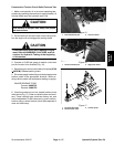
CAUTION
Prevent personal injury and/or damage to equip-
ment. Read all WARNINGS, CAUTIONS, and Pre-
cautions for Hydraulic Testing at the beginning
of this section.
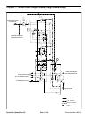
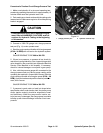
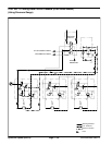
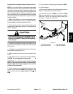
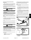
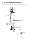
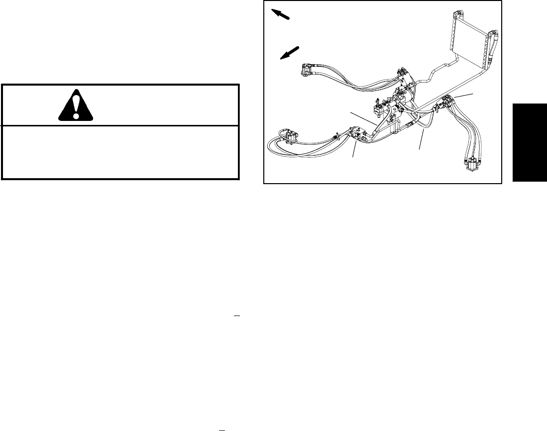
3. Locate deck manifold for gear pump section to be
tested. Disconnect hydraulic hose at deck manifold port
(P1) (Fig. 21).
4. Install tester in serieswith the the disconnected hose
and hydraulic manifold port (P1).
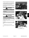
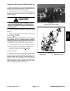
5. Make sure the flow control valve on the tester is fully
open.
6. Start engine and move throttle to full speed (2730 +
30 RPM). Do not engage the cutting units.
IMPORTANT: Do not fully restrict oil f low through
tester. In this test, the flow tester is positioned be-
fore the relief valve. Pump damage can occur if the
oil flow is fully restricted.
7. Watch pressure gauge carefully while slowly closing
the flow control valve until 2000 PSI is obtained. Verify
with a phototac that the engine speed is 2730 +
30
RPM.
8. Flow indication should be approximately 14 GPM.
9. Shut off engine.
10.Disconnect flow testerfrom hydraulichose and man-
ifold port. Reconnect hose to the manifold.
11.If flow was less than 14 GPM or a pressure of 2000
PSIcannot be obtained, check for restriction in thepump
intake line. If line is not restricted, remove gear pump
and repair or replace as necessary.
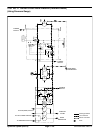
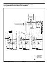
1. Front deck manifold
2. Hyd. hose to front P1
3. Side deck manifold
4. Hyd. hose to side P1
Figure 21
1
3
2
4
FRONT
RIGHT
Hydraulic
System