


Groundsmaster 4000--D Hydraulic System (Rev. B)Page 4 -- 101
Removal
1. Park machine on a level surface, lower cutting units,
stop engine, engage parking brake, and remove key
from the ignition switch.
2. Read the General Precautions for Removing and
Installing Hydraulic System Components at the begin-
ning of the Service and Repairs section of this chapter.
NOTE: To ease reassembly, tag the hydraulic hoses to
show their correct position on the lift cylinder.
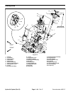
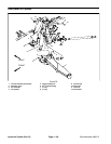
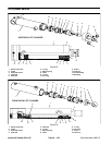
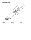
3. Disconnect hydraulic hoses from lift cylinder.
4. Remove lock nut, flat washers, and cap screw that
secure the pin assembly to the lift arm. Remove pin as-
sembly from lift arm and cylinder shaft clevis which will
free lift cylinder from lift arm.
5. Remove one cotter pin from upper lift pin. Pull upper
lift pin from frame and cylinder barrel clevis.
6. Remove lift cylinder from machine.
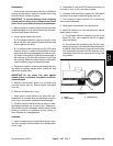
Installation
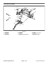
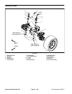
1. Position cylinder barrel clevis to frame and insert up-
per lift pin intoframe andclevis. Securelift pin with cotter
pin.
2. Insert pin assembly through lift arm and cylinder
shaft clevis. Secure pin to lift arm with cap screw, flat
washers, and lock nut.
3. Attach hydraulic hoses to lift cylinder.
4. Fill reservoir with hydraulic fluid as required (seeOp-
erator’s Manual).
5. After assembly is completed, operate lift cylinder to
verify that hydraulic hoses and fittings are not contacted
by anything.
Hydraulic
System