


Groundsmaster 4000−DPage 7 − 8Chassis
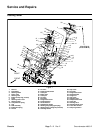
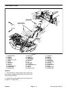
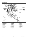
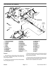
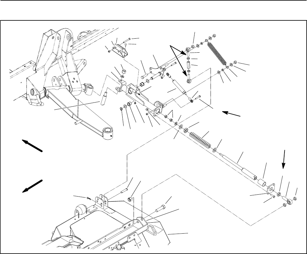
Side Deck Rear Arm Assembly
1. Cutting deck (LH shown)
2. Deck mount (LH shown)
3. Cap screw
4. Lock nut
5. Clevis pin
6. Hair pin
7. Spacer
8. Rod end
9. Jam nut
10. Cap screw
11. Straight bushing
12. Spring shaft
13. Flat washer
14. Compression spring
15. Plastic bearing
16. Lock nut
17. Cap screw
18. Pivot shaft
19. Retaining ring
20. Thrust washer
21. Flange bushing
22. Rear arm (LH shown)
23. Lock nut
24. Lock washer
25. Lock nut
26. Bumper pad
27. Bumper bracket
28. Cap screw
29. Bell crank (LH shown)
30. Damper
31. Damper rod end
32. Cap screw
33. Link tube
34. Lock nut
35. Flat washer
36. Bushing
37. Damper spring
38. Lock nut
39. Carriage screw
40. Grease fitting
41. Jam nut
42. Lock nut
43. Jam nut
44. Rod end
45. Plate
Figure 7
6
18
2
4
5
7
8
14
15
41
22
24
25
28
29
35
36
37
19
21
23
3
34
1
34
11
12
33
32
31
30
38
9
10
13
35
42
26
39
17
27
16
FRONT
RIGHT
Thread locking
Compound
22 to 27 ft−lb
(30 to 37 N−m)
20
40
43
44
13
35
45
114 ft−lb
(155 N−m)
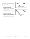
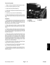
Removal
1. Park machine on a level surface, lower cutting units,
stop engine, engage parking brake, and remove key
from the ignition switch.
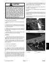
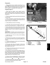
2. Remove hair pin and clevis pin that connects damper
link to cutting deck (Fig. 8).
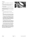
3. Remove cap screw and lock nut that secures rod end
of rear arm to cutting deck. Locate and remove spacer
from each side of rod end.
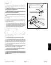
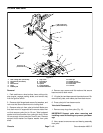
4. Remove lock nut and lock washer that secures rear
arm pivot shaft. Slide pivot shaft from hub and rear arm.
Remove rear arm assembly from machine.