


Groundsmaster 4000--D Hydraulic System (Rev. B)Page 4 -- 61
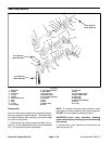
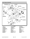
Disassembly
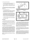
1. Position the pump into a protected jaw vise, clamp-
ing onto the outer portion of the flange, with the cap
screws up. Mark the relationship of the working ports
(for reassembly identification) to the servo control as-
sembly with a scribe. Remove the four cap screws (15)
retaining backplate (20).
2. Lift backplate (20) straight up off drive shaft ( 21) and
housing (19). Remove valve plate (18) from backplate
(20) or from rotating kit assembly (6), still in housing
(19).
3. From backplate (20), remove bypass valve (14), for-
ward relief valve (26), and reverse relief valve (16).
Note: Mark the valves in relationship to the cavity it was
removed, for reassembly purposes.
4. Remove housing gasket (32) from housing (19) or
backplate (20).
5. With pump still in vise, remove the six socket head
screws (17) retaining the servo control assembly (28).
Remove the control assembly and control housing gas-
ket (34) from the housing. Remove orifice plates (30),
noting location for reassembly. Remove nut (22), lock
washer (23), and control arm (27) from servo control in-
put shaft. Note position of control arm for reassembly.
6. To remove rotating kit assembly (6) from housing,
first remove pump from vise holding the rotating kit as-
sembly in position. Lower pump so that the shaft end
(flange end) is up. Setthe rear of housingonto table with
housing flat and rotating kit assembly at rest on table.
(Hole in table, for protruding shaft, is required.) Lift and
remove the housing (19) and drive shaft (21) from rotat-
ing kit assembly (6) and camplate assembly(11).
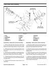
7. Remove camplate (11) from rotating kit assembly (6)
and servo piston follower (8) from camplate (11).
8. Remove the four socket head screws (5) and wash-
ers (31) retaining each cover plate (9 & 10).
9. Remove jam nut (1), washer (29), and seal washer
(4). Hold the servo piston bolt w ith hex key and unscrew
cover plate (10) from bolt.
10.Remove servo pistonassembly (7)and sealsub--as-
semblies (two sets) (37) from housing. Note: Disassem-
bly of servo piston assembly is not required.
11.Remove retaining ring (2) from the front of pump
housing (19). Press the drive shaft (21), shaft seal (25),
and washer (24) from housing. Remove retaining r ing
(3), thrust race (12), thrust bearing (13), second thrust
race (12), and second retaining ring (3) from drive shaft
(21).
12.Remove the two cap screws (42) that secure cradle
sub--assembly inside housing. Move thec radle sub --as-
sembly back--and--forth to release dowel bushings (40)
and remove cradle sub--assembly from housing.
13.Remove button head cap screw (43) to remove
bushing (44) from cradle.
14.Remove remaining plugs from housing.
15.Discard the shaft seal (25), gaskets (32, 33, 34), and
o--rings from all assemblies. Replace with new seals
upon reassembly.
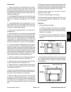
Inspection
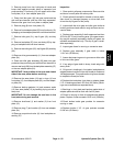
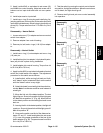
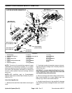
1. Inspect backplate assembly:
A. Check the bearing (45) (press fit) in backplate
(20). If needles remain in cage, move freely, and set-
ting is at the dimension shown in Figure 43, bearing
removal is not required.
B. Check roll pin (38) in backplate (20). If tight and
set to the dimension shownin Figure 43, removalnot
required.
Figure 43
Numbered end
.090 inch
.173 inch
(4.39 mm)
(2.29 mm)
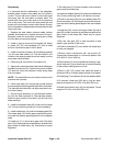
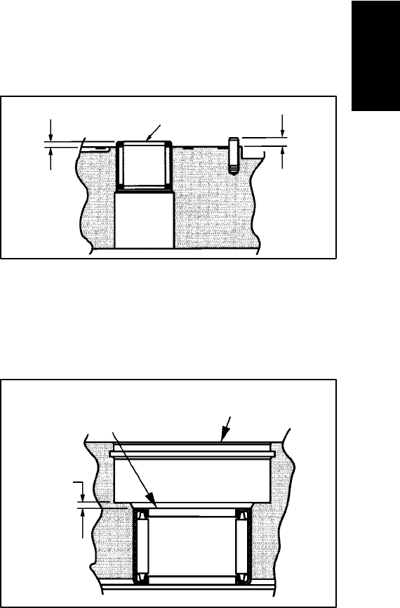
2. Check the bearing (39) (press fit) in pump housing
(19). If needles remain in cage, move freely, and setting
at the dimension shown in Figure 44, bearing removal
is not required.
Figure 44
Numbered end
Flange end of housing
.070 inch
(1.78 mm)
Hydraulic
System