


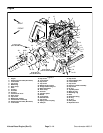

Groundsmaster 4000--D Hydraulic System (Rev. B)Page 4 -- 3
General Information
Hydraulic Hoses
Hydraulic hoses are subject to extreme conditions such
as pressure differentials during operation and exposure
to weather, sun, chemicals, very warm storage condi-
tions, or mishandling during operation or maintenance.
Thesec onditions can cause damage or premature dete-
rioration. Some hoses are more susceptible to these
conditions than others. Inspect the hoses frequently for
signs of deterioration or damage.
When replacing a hydraulic hose, be sure that the hose
is straight (not twisted) before tightening the fittings.
This can be done by observing the imprint on the hose.
Use two wrenches; hold the hose straight with one and
tighten the hose swivel nut onto the fitting with the other.
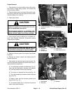
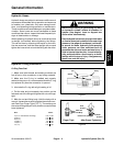
WARNING
Before disconnecting or performing any work
on hydraulic system, relieve all pressure in
system. Stop engine; lower or support box
and/or other attachment(s).
Keep body and handsaway from pin holeleaks
or nozzles that eject hydraulic fluid under high
pressure. Use paper or cardboard, not hands,
to search for leaks. Hydraulic fluid escaping
under pressure can have sufficient force to
penetrate the skin and cause serious injury. If
fluid is injected into the skin, it must be surgi-
cally removed within a few hours by a doctor
familiar with this type of injury. Gangrene may
result from such an injury.
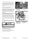
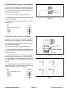
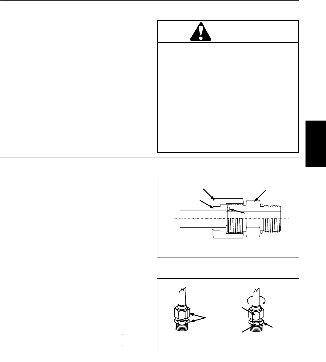
Hydraulic Fitting Installation
O--Ring Face Seal
1. Make sure both threads and sealing surfaces are
free of burrs, nicks, scratches, or any foreign material.
2. Make sure the O--ring is installed and properly
seated in the groove. It is recommended that the O--ring
be replaced any time the connection is opened.
3. Lubricate the O--ring with a light coating of oil.
4. Put the tube and nut squarely into position on the
face seal end of the fitting and tighten the nut until finger
tight.
5. Mark the nut and fitting body. Hold the body with a
wrench. Use another wrenchto tighten the nut to thecor-
rect Flats From Finger Tight (F.F.F.T.). The markings on
the nut and fitting body willverify thatthe connection has
been tightened.
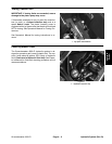
Size F.F.F.T.
4 (1/4 in. nominal hose or tubing) 0.75 +
0.25
6(3/8in.) 0.75+
0.25
8(1/2in.) 0.75+
0.25
10 (5/8 in.) 1.00 +
0.25
12 (3/4 in.) 0.75 +
0.25
16 (1 in.) 0.75 +
0.25
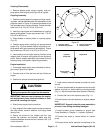
Figure 1
Nut
Sleeve
Seal
Body
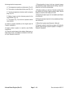
Figure 2
Mark Nut
and Body
Final
Position
Extend Line
Initial
Position
Finger Tight After Proper Tightening
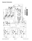
Hydraulic
System