


Groundsmaster 4000−D Page 5 − 11 Electrical System
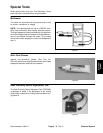
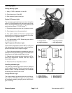
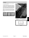
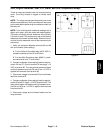
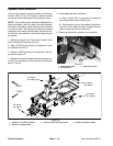
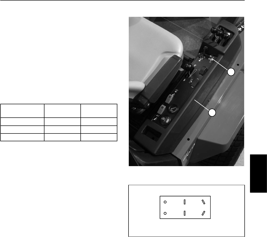
PTO Switch
The PTO switch is attached to the control console next
to the operator seat (Fig. 11).
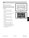
The switch terminals are marked as shown in Figure 12.
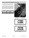
The circuitry of the PTO switch is shown in the chart be-
low. With the use of a multimeter (ohms setting), the
switch functions may be tested to determine whether
continuity exists between the various terminals for each
position. Verify continuity between switch terminals.
NOTE: The PTO ON position requires lifting and push-
ing the lever toward the switch keyway. The PTO OFF
position occurs when the lever is pushed opposite the
keyway.
SWITCH
POSITION
NORMAL
CIRCUITS
OTHER
CIRCUITS
PTO ON 2 + 3 5 + 6
CENTER 1 + 2 5 + 6
PTO OFF 1 + 2 4 + 5
1. PTO switch 2. Control console
Figure 11
1
2
Figure 12
1
32
45 6
BACK OF PTO SWITCH
Electrical
System