


Groundsmaster 4000−D Cutting UnitsPage 8 − 7
Removal
1. Position machine on a clean, level surface. Lower
cutting units, stop engine, engage parking brake, and
remove key from the ignition switch.
NOTE: Removal of clevis pin from deck and height−of−
cut chain is easier if deck is lifted slightly.
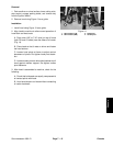
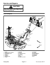
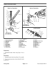
2. Remove hairpin and clevis pin that secure the
height−of−cut chain to the rear of the cutting deck (Fig.
2).
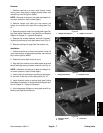
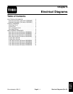
3. Remove hydraulic motor from cutting deck (see Cut-
ting Deck Motor Removal in the Service and Repairs
Section of Chapter 4 − Hydraulic Systems).
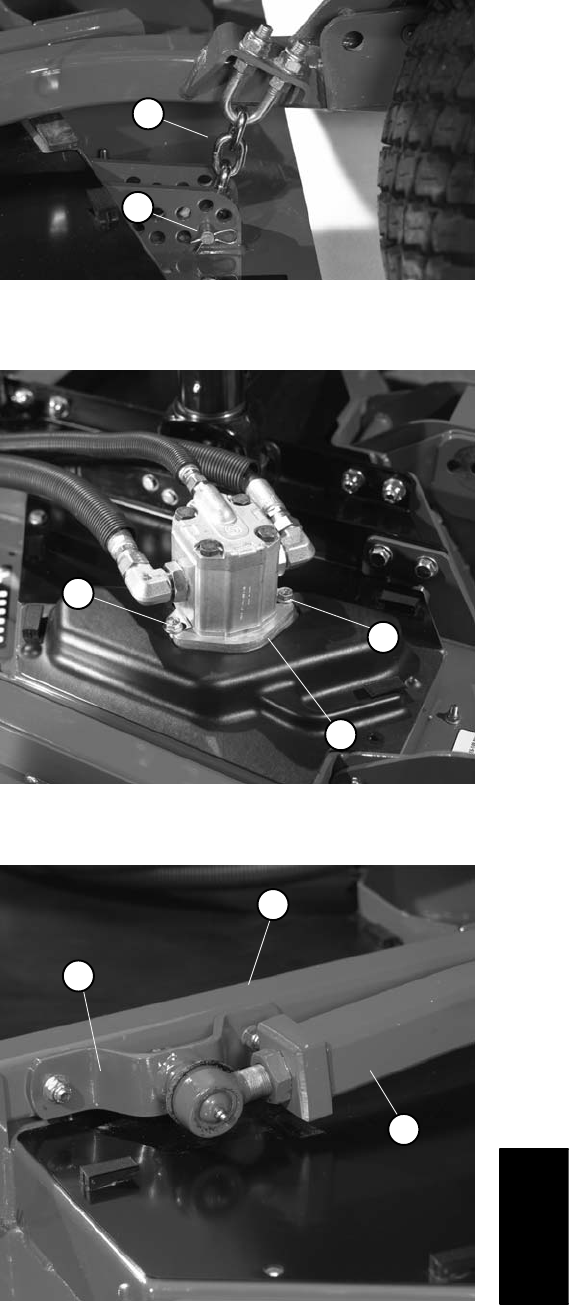
4. Remove cap screws, washers, and lock nuts secur-
ing ball joint mounts to front deck castor arms (Fig. 4).
5. Slide the cutting unit away from the traction unit.
Installation
1. Position machine on a clean, level surface. Lower lift
arms, stop engine, engage parking brake, and remove
key from the ignition switch.
2. Position the front deck to the lift arms.
3. Align ball joint mounts to front deck castor arms and
secure with cap screws, washers, and lock nuts (Fig. 4).
NOTE: Installation of clevis pin to deck and height−of−
cut chain is easier if deck is lifted slightly.
4. Install clevis pin and hairpin that secure the height−
of−cut chain to the rear of the cutting deck (Fig. 2).
5. Install hydraulic motor to cutting deck (see Cutting
Deck Motor Installation in the Service and Repairs Sec-
tion of Chapter 4 − Hydraulic Systems).
6. Lubricate grease fittings on cutting deck and lift as-
sembly (see Operator’s Manual).
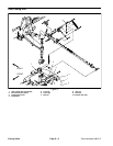
1. Hairpin and clevis pin 2. Height−of−cut chain
Figure 2
1
2
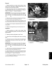
1. Flange head screw 2. Hydraulic motor
Figure 3
1
2
1
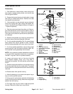
1. Ball joint mount
2. Lift arm
3. Castor arm
Figure 4
1
3
2
Cutting Units