


Rev. E
Groundsmaster 4000−D Page 5 − 27 Electrical System
Cutting Deck Position Switch
The cutting deck position switches on the Groundsmas-
ter 4000−D are located on the traction unit frame (Fig.
40 and 41) and are normally open. The position switch
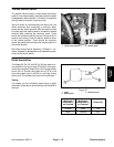
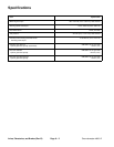
is a powered proximity switch that incorporates an inter-
nal reed switch and relay (see schematic in Figure 42).
The sensing plate is located on the cutting deck lift arm.
The switches for front and side decks are the same al-
though their operation depends on deck location.
When a side cutting deck is raised, the sensing plate is
moved away from the position switch and the switch
opens. The open switch prevents current flow to the side
deck solenoid and keeps the deck from operating.
When the front cutting deck is raised, the sensing plate
is moved near the position switch and the switch closes.
The closed switch prevents current flow to the front deck
solenoid and keeps the deck from operating.
Testing
1. Park machine on a level surface, lower cutting units,
stop engine, engage parking brake, and remove key
from the ignition switch.
2. Locate switch that requires testing and disconnect
switch connector from machine wiring harness.
3. Ground switch connector terminal for black wire and
apply 12 VDC to switch connector terminal for red wire.
4. Using a multimeter, verify that switch connector ter-
minal for blue wire has 12 VDC and terminal for white
wire has 0 VDC.
5. Place metal object near sensing area of switch (op-
posite end from wires). Ground switch connector termi-
nal for black wire and apply 12 VDC to switch connector
terminal for red wire.
6. Using a multimeter, verify that switch connector ter-
minal for blue wire has 0 VDC and terminal for white wire
has 12 VDC.
7. Replace switch as needed.
Adjustment
NOTE: Deck Proximity Switch Adjustment Tool
(TOR4095) can be used for switch adjustment.
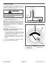
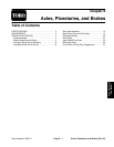
1. Sensing plate on side deck lift arms should be 0.060”
to 0.120” (1.5 to 3.0 mm) from target surface of position
switch.
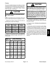
2. On front deck lift arm, slide sensing plate as far from
the lift arm as possible.
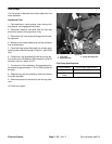
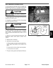
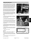
1. Position switch (front)
2. Sensing plate
3. Front lift cylinder
Figure 40
1
2
3
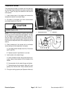
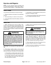
1. Position switch (side) 2. Sensing plate
Figure 41
1
2
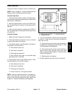
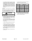
Figure 42
BLACK
BLUE
WHITE
RED
CONNECTORSWITCH
Electrical
System