


Groundsmaster 4000−DPage 7 − 10Chassis
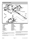
Installation
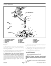
1. Position rear arm assembly to cutting deck and
frame.
2. Slide pivot shaft through rear arm clevis and hub. Se-
cure pivot shaft with lock washer and locknut.
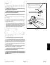
3. Connect damper link to cutting deck with clevis pin
and hair pin (Fig. 8).
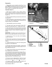
4. Position spacers on both sides of rod end of rear arm
assembly. Secure rod end of rear arm to deck mount
with cap screw and lock nut.
5. Lubricate rear arm grease fittings (see Operator’s
Manual).
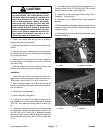
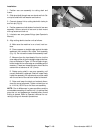
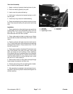
6. Align cutting deck to traction unit as follows:
A. Make sure the machine is on a level, hard sur-
face.
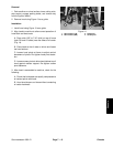
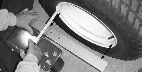
B. Place a square or straight edge against the deck
weldment that contains the castor fork assembly
(Fig. 10). Do not use the castor fork assembly itself.
C. Measure from the inset bead of the rim (not the
outer edge of the rim) to the straight edge at two loca-
tions as indicated in Figure 10. Rim and paint irregu-
larities make the rim outer edge an unreliable point of
measure. These two measurements should be the
same within a tolerance of 1/8” (3 mm).
D. Rotate spring shaft in rear arm assembly until
correct dimension is attained. Shaft will rotate freely
inside the assembly. All adjustments must be made
with the rod end of the rear arm bolted to the deck.
E. Raise and lower the deck and recheck dimen-
sions for correct alignment. Tighten rod end jam nut
to 114 ft−lb (155 N−m) on the rear arm assembly.
NOTE: Due to differences in grass conditions and the
counterbalance setting of traction unit, it is advised that
grass be cut and appearance checked before formal
cutting is started. Refer to Operator’s Manual for cor-
recting cutting unit mismatch procedures.
Figure 10