Groundsmaster 4000−D Page 7 − 7 Chassis
Removal
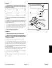
1. Park machine on a level surface, lower cutting units,
stop engine, engage parking brake, and remove key
from the ignition switch.
2. Remove side deck from lift arm (see Side Cutting
Unit in Chapter 8 − Cutting Units).
3. Remove side deck rear arm assembly from pivot hub
(see Side Deck Rear Arm Assembly).
4. Remove lift cylinder pin that secures lift cylinder to lift
arm.
5. Drive out roll pin that retains lift arm pivot shaft. Dis-
card roll pin.
6. Support lift arm and pull lift arm pivot shaft from lift
arm and frame. Locate and remove thrust washers dur-
ing pivot shaft removal.
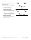
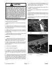
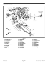
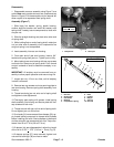
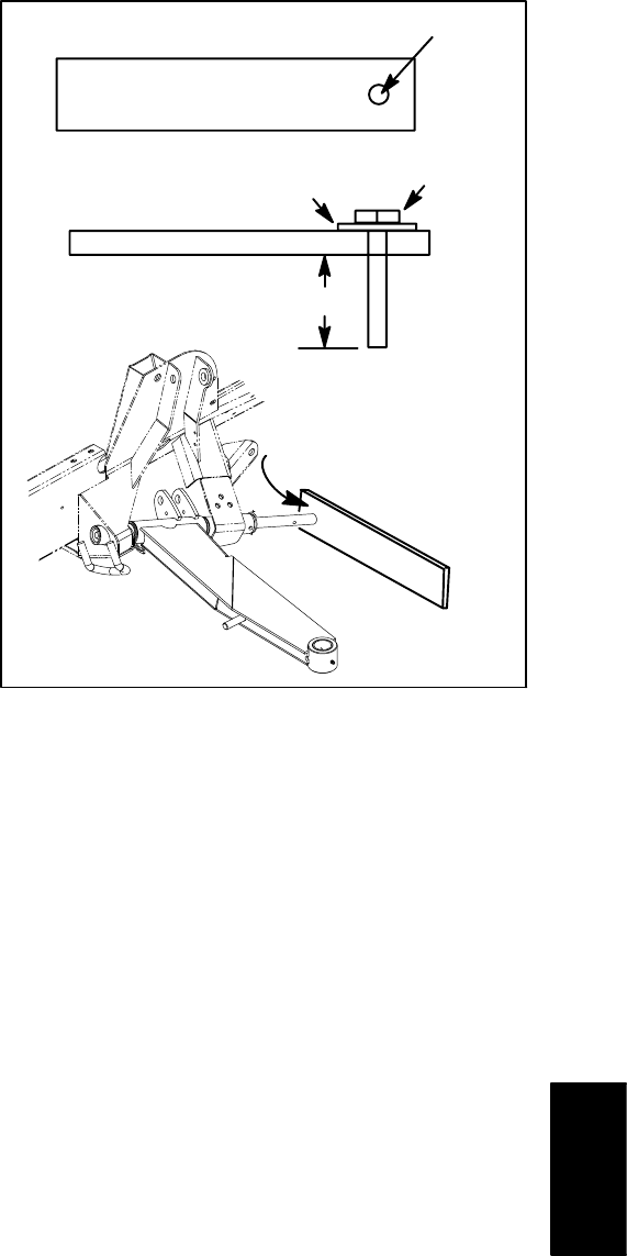
A. If pivot shaft is difficult to remove, fabricate a pull-
er as shown in Figure 6. Attach puller to end of pivot
shaft with the pictured bolt and flat washer. Drive piv-
ot shaft from lift arm and frame with hammer.
7. Remove lift arm from machine.
Installation
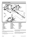
1. Apply anti−seize lubricant to lift arm pivot shaft.
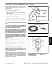
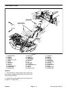
2. Position lift arm to frame with thrust washers properly
placed (Fig. 5). Slide pivot shaft into frame and lift arm
until roll pin holes align.
3. Install new roll pin to secure lift arm pivot shaft.
4. If pivot hub was removed from pivot shaft, slide pivot
hub on shaft. Apply thread locking compound to cap
screw and secure pivot hub with washer and cap screw.
5. Install side deck rear arm assembly (see Side Deck
Rear Arm Assembly).
6. Position and install side cutting deck to machine (see
Side Cutting Unit in Chapter 8 − Cutting Units).
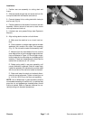
7. Lubricate lift arm grease fittings after assembly is
complete (see Operator’s Manual).
8. After assembly is completed, raise and lower the cut-
ting deck to verify that hydraulic hoses and fittings do not
contact anything.
Figure 6
3” x 12” (3/8” to 1/2” thick) plate steel
9/16” hole
1/2” − 13 UNC bolt
Flat washer
1” to 1 1/8”
Use hammer to drive
pivot shaft from lift arm
Chassis


