


Groundsmaster 4000--D Hydraulic System (Rev. B)Page 4 -- 73
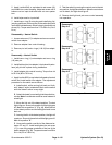
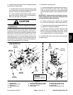
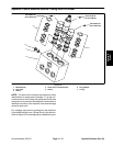
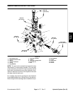
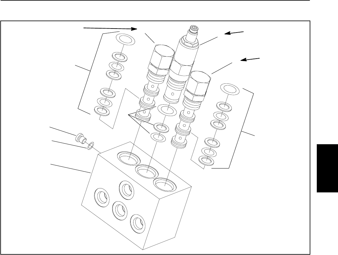
Hydraulic Control Manifold Service: Cutting Deck Lift/Lower
1. Manifold body
2. Pilot valve
3. Seal kit
4. Relief valve (Counterbalance)
5. Seal kit
6. Plug (SAE #2)
7. O--ring
Figure 55
2
6
7
1
2
3
5
4
3
35 to 40 ft--lb
(47to54N--m)
35 to 40 ft--lb
(47to54N--m)
35 to 40 ft--lb
(47to54N--m)
NOTE: The ports on the manifold are marked for easy
identification of components. Example: C1 is the con-
nection port from the LH decklift cylinder andCHG isthe
charge circuit connection (See Hydraulic Schematics to
identify the function of the hydraulic lines and cartridge
valves at each port).
For cartridge valve service procedures, see Hydraulic
Control Manifold Service: 4 Wheel Drive in this section.
Refer to Figure 55 for cartridge valve installation torque.
Hydraulic
System