


Groundsmaster 4000--DHydraulic System (Rev. B) Page 4 -- 76
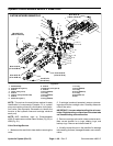
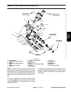
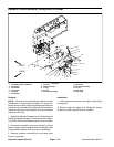
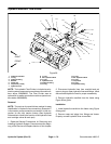
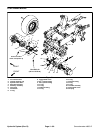
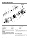
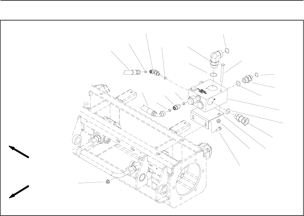
Hydraulic Manifold: Flow Divider
1. Hydraulic manifold
2. O--ring
3. Hydraulic fitting
4. Bracket
5. Flange nut
6. Cap screw (2 used)
7. Hydraulic hose
8. O--ring
9. 90
o
hydraulic elbow
10. O--ring
11. Hydraulic hose
12. Hydraulic fitting
13. O--ring
14. O--ring
15. 90
o
hydraulic elbow
16. O--ring
17. Cap screw
18. O--ring
19. Hydraulic fitting
Figure 58
FRONT
RIGHT
13
10
8
9
19
1
17
2
3
18
14
4
16
12
15
7
11
5
6
5
2
8
NOTE: The hydraulic Flow Divider is included as a hy-
draulic systemcomponent on machines with serial num-
bers above 230000000. The Flow Divider was an
optional kit for earlier production machines (serial num-
bers below 220999999).
Removal
NOTE: The ports on the manifold are marked for easy
identification of hydraulic line connections. Example: P
is the traction pump connection port and M1 is the con-
nection for the front traction motors (See Hydraulic
Schematics to identify the function of the hydraulic lines
and cartridge valves at each port).
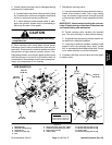
1. Read the General Precautions for Removing and
Installing Hydraulic System Components at the begin-
ning of the Service and Repairs section of this chapter.
2. Disconnect hydraulic lines from manifold and put
caps or plugs on open hydraulic lines and fittings. Label
disconnected hydraulic lines for proper reassembly.
3. Remove hydraulic manifold from the frame using
Figure 58 as guide.
Installation
1. Install hydraulic manifold to the frame using Figure
58 as guide.
2. Remove caps and plugs from fittings and hoses.
Properly connect hydraulic lines to manifold.