


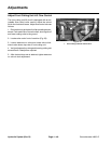


Groundsmaster 4000--DHydraulic System (Rev. B) Page 4 -- 56
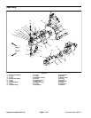
Reassembly
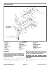
It is important that the relationship of the backplate,
adapter plates, bodies, wear plates and front plate is
correct. The two half moon cavities in the bodies must
face away from the front plate or adapter plate. The
smaller half moon port cavity must be on the pressure
side of the pump. The side of the wear plate with mid
section c ut out must be on suction side of pump. Suction
side of backplate or adapter plate is always the side with
larger port boss.
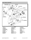
1. Replace the wear plates, pressure seals, backup
gaskets, shaft seal and o--rings as new parts. During re-
assembly, check the scribe mark on each part to make
sure the parts are properly aligned.
2. Install o--rings (4) in groove of front plate (15), adapt-
er plates (23, 24), and backplate (27) with a small
amount of petroleum jelly to hold in place.
3. Install new pressure seals ( 13) and backup gaskets
(14) into new wear plates (12). The flat section in the
middle of the backup gasket must face away from the
wear plate inside the seal.
4. Place plug (8) into pocket of front plate (15).
5. Apply a thin coat of petroleum jelly toboth milled gear
pockets of front body (10). Position body onto front plate
(15) with half moon port cavities in body facing away
from front plate.
NOTE: The small half moon port cavity must be on the
pressure side of pump.
6. Place wear plate (12) into the gear pocket with the
pressure seal and backupgasket againstthe front plate.
The s ide with the mid section cut away must be on suc-
tion side of pump.
7. Dip drive gear assembly (11) and idler gear assem-
bly (16) into clean hydraulic oil. Slip both gear assem-
blies into gear pocket of front body (10) and into front
plate bushings.
8. Install front adapter plate (23) in place on front body
(10). Check positioning marks for correct orientation.
9. Install middle body (19) onto front adapter plate (23).
Place wear plate (12) into the gear pocket with the pres-
sure seal and backup gasket against the front adapter
plate.
10.Install key (17) in slot of drive gear shaft. Dip slip fit
gear (18) in clean hydraulicoil and slide on shaft and into
gear pocket of middle body (19). Check key for proper
alignment.
11.Dip idler gear (21) in clean hydraulic oil and install in
gear pocket of middle body.
12.Install rear adapter plate (24)in place on middle body
(19). Check positioning mark on all sections of pump.
13.Position rear body (26) onto rear adapter plate (24).
Place wear plate (12) into the gear pocket with the pres-
sure seal and backup gasket against the rear adapter
plate.
14.Install key (22) in slot of drive gear shaft. Dip slip fit
gear (20) in clean hydraulicoil and slide on shaft and into
gear pocket of rear body (26). Check key for proper
alignment.
15.Dip rear idler gear (25) in clean hydraulic oil and
install in gear pocket of rear body.
16.Position backplate (27) over shafts until dowel pins
in body are engaged.
17.Secure pump components with cap screws (3).
Torque cap screws evenly in a crisscross pattern fr om
25 to 28 ft --Ib (34 to 38 N--m).
18.Place washer (2) overdrive shaft into housing. Liber-
ally oil shaft seal (1) and install over drive shaft carefully
so that rubber sealing lips are not cut.
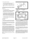
19.Place 1--3/8” O.D. sleeve over shaft and press in
shaft seal .200 in. (5.08mm) belowsurface of front plate.
20.Install plug (7)and washer(9) into rear adapterplate.
21.If removed, install plug (28) with o--ring into back-
plate and torque from 21 to 24 ft--lb (29 to 33 N--m).
22.Install proportional valve (6) into backplate. Torque
plug from 21 to 24 ft--lb (29 to 33 N--m).