


Rev. E
Groundsmaster 4000--D Hydraulic System (Rev. B)Page 4 -- 77
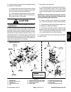
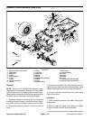
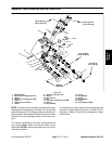
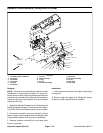
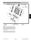
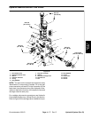
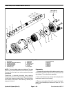
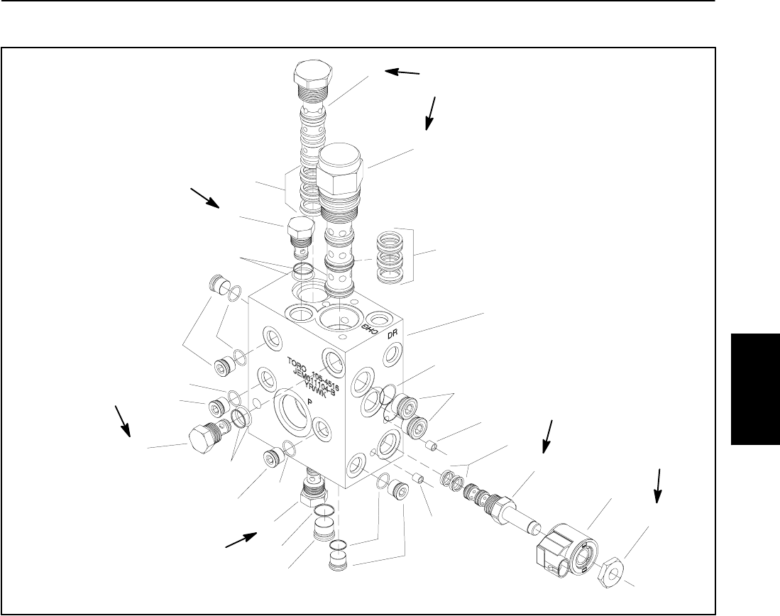
Hydraulic Manifold Service: Flow Divider
1. Flow divider valve
2. Piloted directional valve
3. Seal kit
4. Hydraulic manifold
5. O--ring
6. Plug (SAE #8)
7. Plug (not serviced)
8. Seal kit
9. Solenoid cartridge valve
10. Solenoid coil
11. Nut
12. Plug (SAE #6)
13. O--ring
14. Check valve
15. Seal kit
16. Seal kit
Figure 59
10
8
9
1
2
3
4
12
7
11
5
6
7
16
13
14
15
6
5
14
14
12
12
13
13
12
13
15
50 ft--lb
20 ft--lb
20 ft--lb
20 ft--lb
4to5ft--lb
(67.8 N--m)
(5.4 to 6.8 N--m)
(27.1 N--m)
(27.1 N--m)
(27.1 N--m)
20 ft--lb
(27.1 N--m)
NOTE: The ports on the manifold are marked for easy
identification of components. Example: P2 is the gear
pump connection port and CD is the connection for the
case drain from the deck motors (See Hydraulic Sche-
matics to identify the function of the hydraulic lines and
cartridge valves at each port).
For cartridge valve service procedures, see Hydraulic
Control Manifold Service: 4 Wheel Drive in this section.
Refer to Figure 59 for cartridge valve installation torque.
Hydraulic
System