Groundsmaster 4000--DHydraulic System (Rev. B) Page 4 -- 54
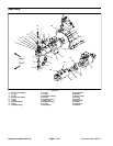
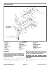
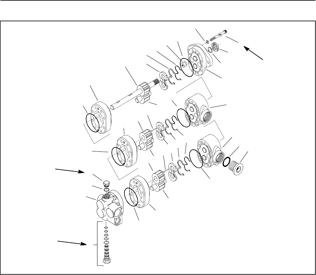
Gear Pump Service
1. Shaft seal
2. Washer
3. Cap screw
4. O--ring
5. Washer
6. Proportional valve
7. Plug
8. Plug
9. O--ring
10. Front body
11. Drive gear assembly
12. Wear plate
13. Pressure seal
14. Backup gasket
15. Front plate assembly
16. Idler gear
17. Key
18. Gear
19. Middle body
20. Gear
21. Idler gear
22. Key
23. Front adapter plate
24. Rear adapter plate
25. Idler gear
26. Rear body
27. Backplate assembly
28. Plug
29. O--ring
Figure 40
4
10
11
12
13
14
8
15
5
3
19
20
21
22
23
24
9
7
25
26
6
1
2
16
17
18
27
4
4
4
4
4
14
13
12
28
29
25 to 28 ft--lb
(34to38N--m)
21 to 24 ft--lb
(29to33N--m)
21 to 24 ft--lb
(29to33N--m)
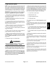
Disassembly
Work in a clean area as cleanliness is extremely impor-
tant when repairing hydraulic pumps. Thoroughly clean
the outside of pump. After cleaning, remove port plugs
and drain oil from pump.
1. Scribe a line, at an angle, across front plate (15), bo-
dies (10, 19, 26), adapter plates (23, 24) and backplate
(27). This will assure proper reassembly.
NOTE: To maintain maximum pump efficiency, keep
body, gears and wear plates for each s ection together.
DO NOT mix parts between different sections.
IMPORTANT: Avoid using excessive clamping
pressure on the pump housing to prevent distorting
the housing.
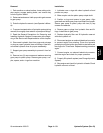
2. Clamp pump in vise, shaft end up and remove the
eight cap screws (3).


