


Groundsmaster 4100--D Hydraulic SystemPage 4 -- 53
Procedure for Lift/Lower Circuit Relief Pressure
Test
NOTE: Before attempting to check or adjust lift pres-
sure, make sure that counterbalance pressure is cor-
rectly adjusted.
1. Make sure hydraulic oil is at normal operating tem-
perature by operating the machine for approximately 10
minutes. Make sure the hydraulic tank is full.
2. Parkmachineon a level surface with thecuttingdeck
lowered and off. Make sure engine is off and the parking
brake is engaged.
CAUTION
Prevent personal injury and/or damage to equip-
ment. Read all WARNINGS, CAUTIONS and Pre-
cautions for Hydraulic Testing at the beginning
of this section.
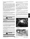
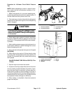
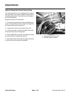
3. Raise s eat to gain access to hydraulic test fitting.
Connect a 5,000 PSI (345 bar) gauge to lift circuit test
port(Fig.41). Route gauge hosetoallow seat tobesafe-
ly lowered.
4. After installing pressure gauge, start engine and run
at idle speed. Check for hydraulic leakage and correct
before proceeding with test.
5. Sit on the seat and operate the engine at full speed
(2870 RPM).
6. While sitting on the seat, pull lift lever back to raise
the cutting deck. Momentarily hold the lever with the lift
cylinder fully retracted (deck fully raised) while looking
at the gauge.
GAUGE READING TOBE2500to2550PSI(173 to
175 bar).
7. Stop the engine and record test results.
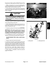
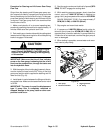
8. If pressure is too high, adjustrelief valve in lift control
valve by rotating counterclockwise (Figure 42). If pres-
sure is too low, check for restriction in pump intake line.
Check the lift cylinder for internal leakage. If cylinder is
not leaking, adjust the relief valve by rotating clockwise.
If pressure is still too low, pump or lift cylinder(s) should
be suspected of wear, damage or inefficiency.
9. When testing is completed, disconnect pressure
gauge from test port.
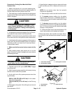
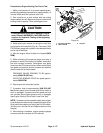
1. Fan drive manifold
2. Lift circuit test port
3. Lift control valve
4. Relief valve
Figure 41
1
2
3
4
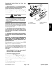
1. Control valve assembly
2. Relief valve assembly
3. Washers
4. Spring
5. Poppet
Figure 42
2
3
1
4
5
Hydraulic
System