


Groundsmaster 4100--D Hydraulic SystemPage 4 -- 47
Procedure for Cutting Deck Gear Pump Flow Test
NOTE: Overa period of time, the gearsandwearplates
in the gear pump can wear. A worn pump will by--pass
oil and make thepumplessefficient. Eventually,enough
oil losswilloccur to cause thecutting deck motorstostall
under heavy cutting conditions. Continued operation
with a worn, inefficient pump can generate excessive
heat and cause damage to the seals and other compo-
nents in the hydraulic system.
1. Make sure hydraulic oil is at normal operating tem-
perature by operating the machine for approximately 10
minutes. Make sure the hydraulic tank is full.
2. Parkmachineon a level surface with thecuttingdeck
lowered and off. Make sure engine is off and the parking
brake is engaged.
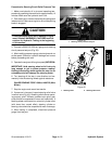
CAUTION
Prevent personal injury and/or damage to equip-
ment. Read all WARNINGS, CAUTIONS and Pre-
cautions for Hydraulic Testing at the beginning
of this section.
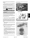
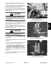
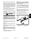
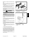
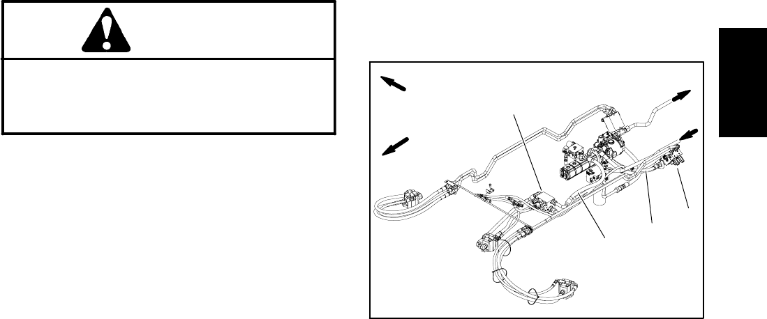
3. Locate deck manifold for gear pump section to be
tested. Disconnect hydraulic hose at deck manifold port
(P1) (Fig. 36).
4. Install tester with pressure gauges and flow meter in
series with the the disconnected hose and hydraulic
manifold port (P1).
5. Make sure the flow control valve on the tester is
fully open.
6. After installing tester, start engine and run at idle
speed. Check for hydraulic leakage and correct before
proceeding with test.
IMPORTANT: Do not run engine at full speed during
testing. At full engine speed, cutting deck gear
pump output can exceed 15 GPM and cause tester
damage.
7. Using a phototac, adjustengine speedto 2400RPM.
Do not engage the cutting deck.
IMPORTANT: Do not fully restrict oil flow through
tester. In this test, the flow tester is positioned be-
fore the relief valve. Pump damage can occur if the
oil flow is fully restricted.
8. Watch pressure gauge carefully while slowly closing
the flow control valve until 2000 PSI is obtained. Verify
with a phototac that the engine speed is 2400 RPM.
9. For a normal pump, gear pump flow should be
approximately 14 GPM. Shut off engine. Record test re-
sults.
10.If measured flow is lessthan12 GPM orifa pressure
of 2000 PSI cannot be obtained, check for restriction in
the pump intake line.Ifline is not restricted, removegear
pump and repair or replace as necessary.
11.Disconnectflow tester from hydraulic hose and man-
ifold port. Reconnect hose to the manifold.
12.Repeat test for second pump section if required.
1. Center deck manifold
2. Hyd. hose to front P1
3. LH wing deck manifold
4. Hyd. hose to side P1
Figure 36
FRONT
RIGHT
TO OIL COOLER
1
4
2
3
Hydraulic
System