


Groundsmaster 4100--D Page 5 -- 35 Electrical System
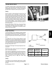
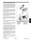
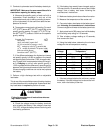
Cutting Deck Raise and Lower Switches
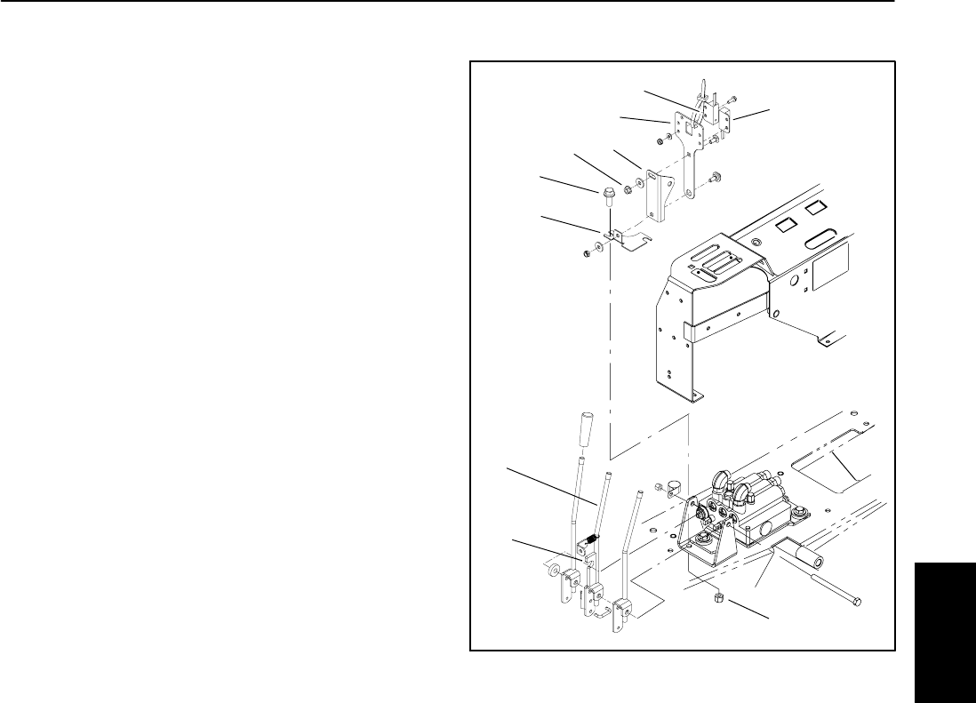
The deck raise and lower switches are normally open
proximity switches that are located under the console
housing (Fig.56).These identical switchesaremounted
inoppositedirections sotheircircuit logicdiffers.The ac-
tuator for the switches is on the center deck lift/lower le-
ver. The raise and lower s witches are used in
conjunction with the down latching relay to provide cur-
rent to the PTO switch.
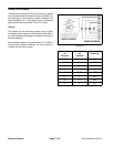
The deckraiseswitch is closed when the center decklift/
lower lever is either in the neutral (center) position or
pushed to the lower (forward) position. Ifthe center deck
lift/lower lever is pulled to the raise (rear) position, the
deck raise switch opens.
The deck lower switch is closed when the center deck
lift/lower lever is pushed to the lower (forward) position.
If the center deck lift/lower lever is in either the neutral
(center) position or the raise (rear) position, the deck
lower switch remains open.
Once the down latching relay is energized by lowering
the cutting deck, the cutting deck raise switch and diode
D3 provide a latching circuit to keep therelay energized.
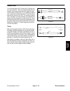
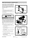
Testing
1. Park machine on a level surface, lower cutting deck,
stop engine, engage parking brake and remove key
from the ignition switch.
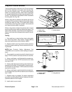
2. Remove console cover and locate cutting deck raise
or lower switch to be tested. Disconnect switch connec-
tor from machine wiring harness.
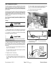
3. Check switch continuity by connecting a multimeter
(ohms setting) across the switch connector terminals.
4. The raise switch should be closed (continuity) when
the center deck lift/lower lever is in the neutral position.
As the lift/lower lever is slowly pulled back, the raise
switch should open (nocontinuity) after the lever has re-
moved all free play (with no spool movement in lift/lower
control valve) but before the deck is lifted.
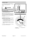
5. The lower switch should be open (no continuity)
when the center deck lift/lower lever is in the neutral
position. As the lift/lower lever is slowly pushed forward,
the lower switch should close (continuity) before the le-
ver reaches full forward travel.
6. For switch adjustment procedure, see Cutting Deck
Raise and Lower Switches in the Adjustments section of
this chapter.
7. Connect switch to wiring harness. Install console
cover to machine.
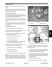
1. Deck lower switch
2. Deck raise switch
3. Switch plate
4. Lever bracket
5. Flange nut
6. Flange bolt (2 used)
7. Tab plate
8. Deck lift/lower lever
9. Switch actuator
10. Lock nut (2 used)
Figure 56
9
2
4
3
1
8
7
6
5
10
Electrical
System