


Groundsmaster 4100--DHydraulic System Page 4 -- 20
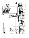
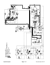
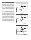
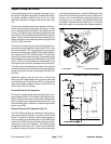
Mow Circuit Cutting Deck Blade Braking
When theoperatorturns the PTOswitch OFF or if adeck
is raised with the PTO switch ON, deck control manifold
solenoid valve (S) is de--energized causing logic car-
tridge (LC1)toshift (refer toinformationin PTO MowCir-
cuit in this section). This shifted cartridge allows oil
return out manifold port P2. At the same time, solenoid
valve (S) in its neutral position prevents any sense line
flow through the s pool which causes the logic cartridge
LC2 to shift to its neutral position blocking return flow
from the deckmotor and slowing thecutting blades (Fig.
10).
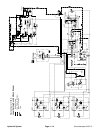
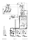
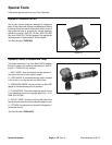
The inertia oftherotatingcutting blades, however, effec-
tively turns the deck motor into a pump causing an in-
crease in pressure as the flow from the motor comes up
againsttheclosed logic cartridge (LC2).Whenthis pres-
sure builds to approximately 600 PSI (41 bar), relief
valve (RV2) opens which allows a small amount of hy-
draulic flow to return to tank through a manifold sensing
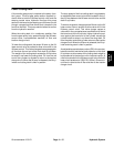
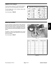
line (Fig. 11). This flow causes a pressure increase that
shifts logic cartridge LC2 to once again allow oil flow
from the motor (Fig. 12). When motor return pressure
drops below 600 PSI (41 bar), relief valve (RV2) reseats
and causes LC2 to close again blockingreturn flow from
the deck motor to further slow the cutting blades. This
action of thebrakereliefvalveopeningandthelogiccar-
tridge shifting occurs several times in a very s hort time
frame as the blades finally come to a stop. Once the
blades have stopped, logic cartridge LC2 remains in the
neutral position to k eep the deck motor from rotating.
Figure 10
MOTOR
CD
DECK
G
RV1
RV2
LC2
LC1
S
P1
P2
M1
M2
DECK MANIFOLD
Figure 11
MOTOR
CD
DECK
G
RV1
RV2
LC2
LC1
S
P1
P2
M1
M2
DECK MANIFOLD
Figure 12
DECK MANIFOLD
MOTOR
CD
DECK
G
RV1
RV2
LC2
LC1
S
P1
P2
M1
M2