


Groundsmaster 4100--D Page 7 -- 7 Chassis
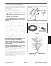
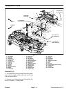
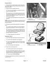
Removal (Fig. 5)
1. Park machine on a level surface, lower cutting deck,
stop engine, apply parking brake and remove key from
the ignition switch.
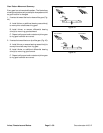
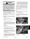
2. Remove seat from seat suspension:
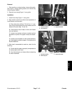
A. Disconnect seat electrical connectors from ma-
chine wire harness (Fig. 6).
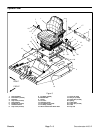
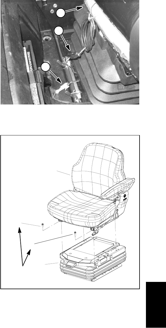
B. Remove four (4) Torx head screws that secure
seat to seat suspension (Fig. 7). Note that the screw
near the seat adjustment handle is longer than the
other three (3) screws.
C. Lift seat from seat suspension and remove from
machine.
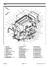
NOTE: Most of the seat suspension components can
be serviced with the seat suspension base mounted to
the frame platform.
3. Ifnecessary,remove seat suspensionfrom seatplat-
form:
A. Tilt seat to gain access to mounting fasteners.
Support seat suspension to prevent it from falling.
B. Remove four (4) cap screws and flange nuts that
secure seat suspension to seat plate. Note that two
(2) r--clamps that retain wire harness are secured
with seat suspension fasteners.
C. Lift seat suspension from machine.
Installation (Fig. 5)
1. If removed, install seat suspension to seat platform:
A. Position seat suspension onto seat plate.
B. Secureseat suspension and two(2)wire harness
r--clamps to seat platform with four (4) cap screws
and flange nuts.
C. Lower seat plate and suspension.
2. Install seat to seat suspension:
A. Carefully position seat to seat suspension.
B. Secure seat to seat suspension with four (4) Torx
head screws (Fig. 7). Make sure that longer screw is
positioned near the seat adjustment handle.
C. Torque screws 18 ft--lb (25 N--m).
3. Connect seat electrical connectors to machine wire
harness (Fig. 6).
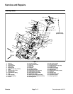
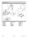
1. Operator seat
2. Seat switch connector
3. Suspension connector
Figure 6
1
2
3
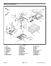
1. Seat
2. Suspension assembly
3. Screw (M8x12) (3 used)
4. Screw (M8x16)
Figure 7
2
3
1
4
18 ft--lb
(25 N--m)
Chassis