


Groundsmaster 4100--D Hydraulic SystemPage 4 -- 35
Procedure for Traction Circuit Relief Pressure Test
1. Make sure hydraulic oil is at normal operating tem-
perature by operating the machine for approximately 10
minutes. Make sure the hydraulic tank is full.
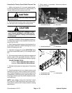
CAUTION
Move machinetoanopena rea, away from people
and obstructions.
2. Drive machine to an open area, lower cutting deck,
turn the engine off and engage the parking brake.
CAUTION
Prevent personal injury and/or damage to equip-
ment. Read all WARNINGS, CAUTIONS and Pre-
cautions for Hydraulic Testing at the beginning
of this section.
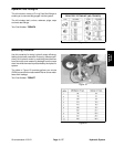
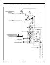
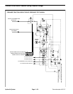
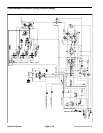
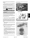
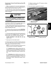
3. Connecta 10,000PSI(700bar)gaugetotractioncir-
cuit test port for function to be checked (Forward or Re-
verse: Fig. 22 or 23).
4. After installing pressure gauge, start engine and run
at idle speed. Check for hydraulic leakage and correct
before proceeding with test.
5. Operate the engine at full speed (2870 RPM) .Make
sure that transport/4WD switch is in the transport posi-
tion.
6. Siton seat, apply brakes fully and slowlydepress the
traction pedal in the appropriate direction. While pu-
shing traction pedal, look at pressure reading on gauge:
GAUGE READING TO BE:
Forward: 3750 to 4250 PSI (259 to 293 bar)
Reverse: 4750 to 5250 PSI (328 to 362 bar)
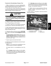
7. Release traction pedal and stop engine. Record test
results.
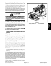
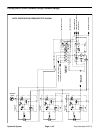
8. If traction pressure is too low, inspect traction pump
relief valves (Fig. 24). Clean or replace valves as neces-
sary.Thesecartridgetype valves are factory set and are
notadjustable.Ifrelief valves are in goodcondition,trac-
tion pump or wheel motors should be suspected of wear
and inefficiency.
NOTE: Seal leakage across pilot directional valves
PD1 and PD2 in 4WD manifold can also cause low for-
ward traction pressure with reverse pressure meeting
specifications.
9. When testing is completed, disconnect pressure
gauge from test port.
1. Forward traction port 2. LH front tire
Figure 22
1
2
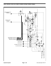
1. Reverse traction port 2. RH front tire
Figure 23
1
2
1. Forward relief valve
2. Reverse relief valve
3. Traction pump
Figure 24
FRONT
RIGHT
1
2
3
Hydraulic
System