


Groundsmaster 4100--DPage 5 -- 34Electrical System
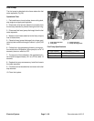
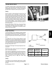
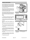
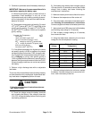
Wing Deck Position Switches
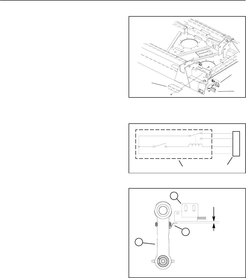
The wing deck position switches on the Groundsmaster
4100--D are attached to the center deck housing ( Fig.
53) and are normally open. The wing deck position
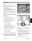
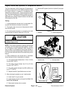
switch is a powered proximity switch that incorporates
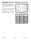
an internal reed switch and relay (see schematic in Fig-
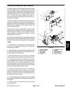
ure 54). The actuator for the position switch is bolted to
the wing deck link (Fig. 55).
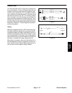
When a wing deck is lowered, the actuator tab on the
wing deck link is positioned close to the position switch
causing the switch to close. The closed switch allows
current flow to the wing deck hydraulic valve solenoid
and allows that wing deck to operate.
When a wing deck is raised, the actuator tab is moved
away fromtheposition switch and the switch opens.The
open switch prevents current flow to the wing deck hy-
draulicvalvesolenoidandkeeps thatwing deckfrom op-
erating.
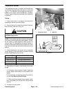
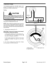
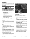
Testing
1. Park machine on a level surface, lower cutting deck
and raise wing decks. Stop engine, engage parking
brake and remove key from the ignition switch.
2. Remove switch cover from deck to allow access to
switch that requires testing. Disconnect switch from wir-
ing harness.
NOTE: Deck Proximity Switch Adjustment Tool
(TOR4095) can be used for switch testing and adjust-
ment.
3. Ground switch connector terminal for black wire and
apply 12 VDC to switch connector terminal for red wire.
4. Using a multimeter, verify that switch connector ter-
minal for blue wire has 12 VDC and terminal for white
wire has 0 VDC.
5. Placeametalobjectnearsensingareaofswitch(op-
posite end from wires). Ground switch connector termi-
nal for black wire and apply 12 VDC to switch connector
terminal for red wire.
6. Using a multimeter, verify that switch connector ter-
minal for blue wire has 0 VDC and terminal for white wire
has 12 VDC.
7. Replace switch as needed. For switch adjustment
procedure, see Wing Deck Position Switches in the Ad-
justments section of this chapter.
8. Install switch cover to deck.
1. Switch cover
2. Position switch
3. Switch bracket
Figure 53
1
2
3
Figure 54
BLACK
BLUE
WHITE
RED
CONNECTOR
POSITION SWITCH
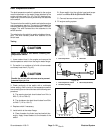
1. Position switch
2. Actuator tab
3. Wing deck link
Figure 55
0.188”
(4.8 mm)
3
1
2