


Groundsmaster 4100--DPage 5 -- 20Electrical System
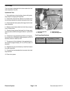
Glow and Power Relays
The Groundsmaster 4100--D uses two (2) identical re-
lays to control electrical power circuits. The glow relay
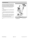
is attached to the the right side of the fuel tank support
under the hood. The power relay is attached to the con-
trol panel under the console housing.
The glow relay supplies electrical power for the engine
glow plugs when energized. The start relay is energized
by the glow plug controller.
The power relay supplies electrical power for fuses F9
(TEC--5002 outputs), F10, F11 and F12. The main pow-
er relay is energized when the ignition switch is in the
START or RUN position.
Testing
1. Park machine on a level surface, lower cutting deck,
stop engine, apply parking brake and remove key from
ignition switch.
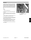
2. Open hood to gain access to relay.
3. Locate relay and disconnect the machine wire har-
ness connector from the relay. Remove relay from ma-
chine for easier testing.
NOTE: Prior to taking small resistance readings with a
digital multimeter, short the meter test leads together.
The meter will display a small resistance value (usually
0.5 ohms or less). This resistance is due to the internal
resistance of the meter and test leads. Subtract this val-
ue from from the measured value of the component you
are testing.
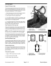
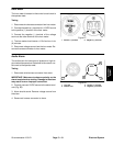
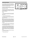
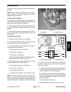
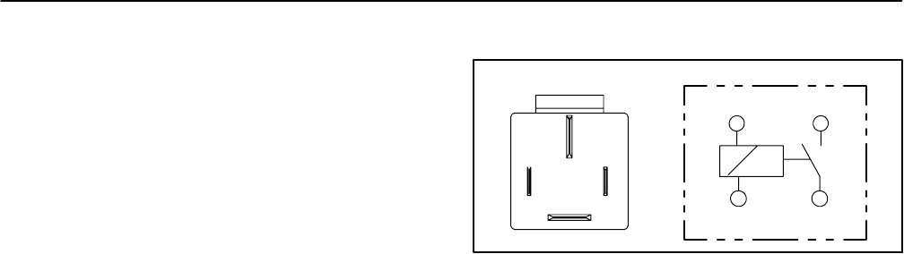
4. Verify coil resistance between terminals 85 and 86
with a multimeter (ohms setting) (Fig. 29). Resistance
should be approximately 72 ohms.
5. Connectmultimeter (ohms setting) leads to relay ter-
minals 30 and 87. Ground terminal 86 and apply +12
VDCtoterminal 85.Therelay should havecontinuitybe-
tween terminals 30 and 87 as +12 VDC is applied to ter-
minal 85. The relay should not have continuity between
terminals 30 and 87 as +12 VDC is removed from termi-
nal 85.
6. After testing is complete, install relay to frame and
connect wire harness to relay.
7. Close and secure hood.
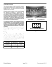
Figure 29
86 87
85 30
85 86
87
30