


Groundsmaster 4100--DHydraulic System Page 4 -- 136
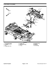
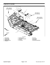
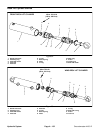
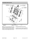
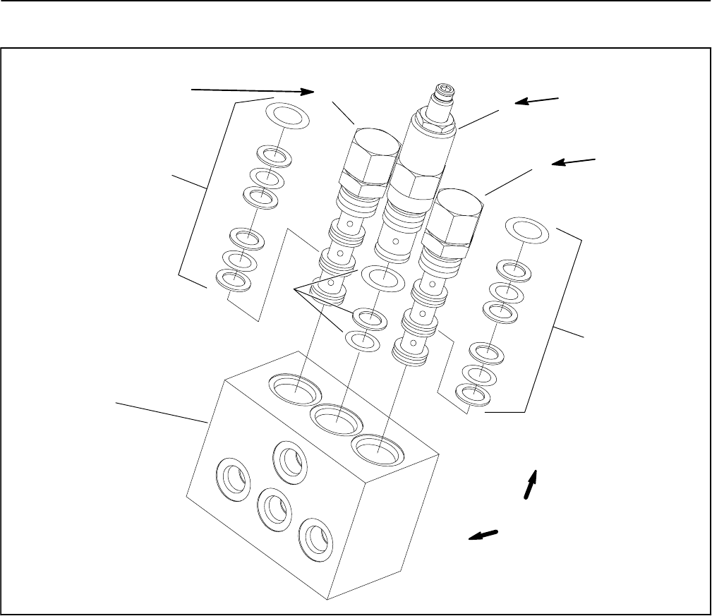
Counterbalance Manifold Service
1. Manifold body
2. Pilot valve
3. Seal kit
4. Relief valve (counterbalance)
5. Seal kit
Figure 95
2
1
2
3
5
4
3
35 to 40 ft--lb
(47to54N--m)
35 to 40 ft--lb
(47to54N--m)
35 to 40 ft--lb
(47to54N--m)
FRONT
UP
NOTE: The ports on the manifold are marked for easy
identification of components. Example: C1 is the con-
nection port fromtheLH deck lift cylinder and CHGisthe
charge circuit connection (See Hydraulic Schematic in
Chapter 9 -- Foldout Drawings to identify the function of
the hydraulic lines and cartridge valves at each port).
Counterbalance Manifold Service (Fig. 95)
For cartridge valve service procedures, see 4WD Man-
ifold Service in this section. Refer to Figure 95 for coun-
terbalance manifold cartridge valve installation torque.