


Groundsmaster 4100--D Cutting DeckPage 8 -- 13
Cutting Deck Link Service
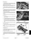
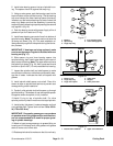
Disassembly (Fig. 10)
1. Press bushings from top of link.
2. Remove dust cap and retaining ring from link.
3. Press tapered stud with spherical bearing, flat wash-
ers and flange nut from link.
4. Remove flange nut and press spherical bearing from
tapered stud.
Assembly (Fig. 10)
1. Install new spherical bearing onto tapered stud. Se-
cure bearing with flange nut. Torque nut from 30 to 40
ft--lb (41 to 54 N--m).
2. Position flat washer in both sides of spherical bear-
ing.
3. Press tapered stud with spherical bearing, flat wash-
ers and flange nut into link. Secure spherical bearing
into link with retaining ring.
4. Press bushings into top bore of link.
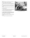
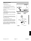
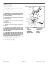
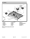
5. If cap screw and jam nut were removed from rear
link,installcap screw toallow 1.625” (41.3 mm)between
the head of the screw and the side of the link (Fig. 11).
6. After link is installed on deck, check distance be-
tween center deck blade and wing deck blade. Readjust
cap screw and jam nut on rear link if needed (see Wing
Deck Service in this Chapter).
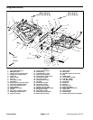
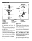
1. Link
2. Bushing (2 used)
3. Tapered stud
4. Spherical bearing
5. Flat washer (2 used)
6. Retaining ring
7. Flange nut
8. Dust cap
Figure 10
30 to 40 ft--lb
(41to54N--m)
1
3
6
7
4
5
2
8
1. Rear link
2. Cap screw
3. Hex jam nut
Figure 11
1.625”
(41.3 mm)
1
2
3
Cutting Deck