


Groundsmaster 4100--D Hydraulic SystemPage 4 -- 13
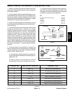
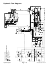
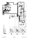
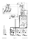
Traction Circuit: Transport (2WD)
The traction circuit piston pump is a variable displace-
ment pump that is directly coupled to the engine fly-
wheel. Pushing the traction pedal engages a hydraulic
servo valve which controls the variable displacement
piston pump swash plate to create a flow of oil. This oil
is directed to the front wheeland rear axle motors.Oper-
ating pressure on the high pressure side of the closed
traction circuit loop is determined by the amount of load
developed atthe fixed displacement wheelandaxle mo-
tors. As the load increases, circuit pressure can in-
crease to relief valve settings: 4000 PSI (274 bar) in
forward and 5000 PSI (343 bar) in reverse. If pressure
exceeds the relief setting, oil flows through the relief
valve to the low pressure side of the closed loop traction
circuit. The traction circuit provides operation in either
4WD (mow) or transport (2WD).
Traction circuit pressure (forward and reverse) can be
measured at test ports on the sides of the machine.
The traction circuit pump and motors use a small
amount of hydraulic fluid for internal lubrication. Fluid is
designed to leak across traction pump and motor com-
ponents into the case drain. This leakage results in the
loss ofhydraulicfluid from the closedlooptractioncircuit
that must be replaced. The charge circuit is designed to
replace this traction circuit leakage.
The gear pump section that supplies o il to the steering
and lift/lower circuits also provides charge oil for the
traction circuit. This gear pump is driven directly off the
traction pump.It provides a constant supply ofchargeoil
to the traction circuit to make up for oil that is lost due to
internal leakage in the traction pump and motors.
Charge pump flow is directed through the oil filter and to
the low pressure side of the closed loop traction circuit.
A filter bypass valve allows charge oil flow to the closed
loop if the filter becomes plugged. Charge pressure is li-
mited to 250 PSI (17 bar) by a relief valve located in the
oil filter manifold. Charge pressure can be measured at
the charge circuit pressure test port on the oil filter man-
ifold.
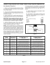
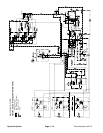
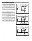
Forward Direction
With the transport/4WD switch in the transport position,
solenoid valve (SV) in the 4WD control manifold is ener-
gized. The solenoid valve spool shifts to direct charge
pressure that shifts the PD1 and PD2 control valve
spools. The shifted PD1 valve prevents hydraulic flow
from the piston pump to the rear axle motor. With flow
blocked to the rear axle motor, all pump flow is directed
to the front wheel motors to allow a higher transport
speed in the forward direction.
Without flow to the rear axle motor, the rotating rear
wheels drive the axle motor so it acts like a pump. Inlet
oil to the axle motor is provided by a check valve that al-
lows charge oil into the rear axle motor circuit. Oil leav-
ing the axle motor enters the 4WD control manifold at
port M2 and is directed back to the axle motor through
the shifted PD1 cartridge and manifold port M1. To allow
for rearwheelloop cooling when inforwardtransportop-
eration, a small amount of oil exits through the shifted
PD1 and PD2 cartridges that returns to the reservoir.
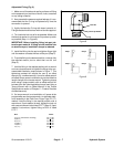
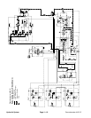
Reverse Direction
The traction circuit operates essentially the same in re-
versetransport(2WD) asitdoes inthe forward direction.
However, the flow through the circuit is reversed. The
shifted solenoid valve (SV) and directional valves PD1
and PD2 in the 4WD manifold prevent oil flow from the
rear axle motor. Oil flow from the hydrostat is therefore
directed to only the front wheel motors. This oil drives
the front wheel motors in the reverse direction and then
returns to the hydrostat. Oil circulation through the rear
axle motor loop is the same as in the transport (2WD)
forward direction.
Hydraulic
System