


Groundsmaster 4100--DPage 6 -- 22Axles, Planetaries and Brakes
Differential Shafts
The following procedures assume the rear axle assem-
bly has been removed from the machine (see Rear Axle
Assembly Removal in this section).
Differential Shaft Removal
IMPORTANT: Do not interchange right and left dif-
ferential shaft assemblies.
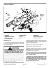
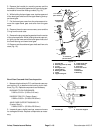
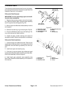
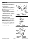
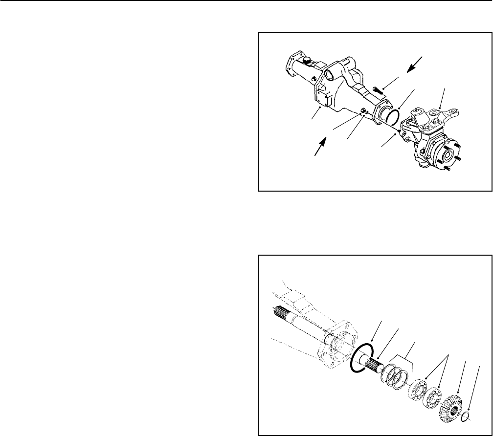
1. Remove the mounting screws, nuts and lock wash-
ers. Remove the bevel gear case/axle c ase assembly
and O-ring from the axle support (Fig. 25).
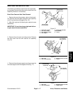
2. Markandpullthe differential shaftassemblyfromthe
axle support.
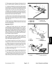
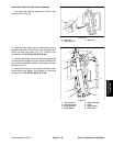
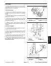
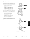
3. Remove the retaining ring and bevel gear (Fig 26).
4. Drive the differential shaft out of the bearings. Re-
move the bearings and bearing shims.
5. Inspect all gears, shafts, bearings and cases for
damage and wear. Replace components as necessary.
Differential Shaft Installation
1. Press bearings onto differential shaft. Place correct
combination of bearing shims in axle support and drive
differential shaft and bearing assembly into axle sup-
port.
2. Install bevel gear and retaining ring.
3. Coat new O-ring with grease. Align differential shaft
splines with differential gear assembly and slide differ-
ential shaft assembly onto axle support.
4. Install bevel gear case/axle case assembly (see
Bevel Gear Case/Axle Case Assembly in this section of
this manual).
1
2
3
4
5
6
1. Cap screw (4 used)
2. Lock nut (2 used)
3. Lock washer (2 used)
4. Axle support
5. Bevel gear/axle case
assembly
6. O-ring
7. Stud (2 used)
Figure 25
7
35 to 41 ft--lb
(47to56N--m)
35 to 41 ft--lb
(47to56N--m)
1
2
3
4
5
6
1. Retaining ring
2. Bevel gear
3. Differential shaft
4. Bearing
5. Bearing shims
6. O-ring
Figure 26