


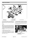

Groundsmaster 4100--DPage 5 -- 30Electrical System
Temperature Gauge
The temperature gauge can be tested using a new
gauge as a substitute or with the use of a DC voltage
source and a variable resistance box.
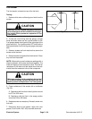
Testing
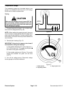
CAUTION
Make sure the voltage source is turned OFF be-
fore connecting variable resistance to the elec-
trical circuit to avoid electrical shock and to pre-
vent damaging the gauge.
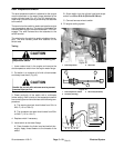
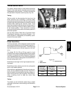
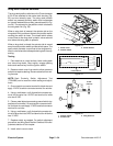
1. Connect temperature gauge to the v ariable resis-
tance and DC voltage source (Fig. 46).
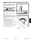
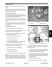
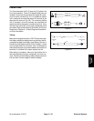
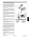
NOTE: When reading the gauge test point, there are
two white dots on the gauge face below the edge of the
glass cover for each test point. For each variable resist-
ance setting, the needle must be pointed between the
two white dots.
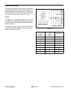
2. Take test point readings (Fig. 47).
IMPORTANT: Allow circuit to warm up for at least 5
minutes before taking test readings.
A. Set variable resistance to 71 ohms. Apply a 14 +
0.01 VDC to the circuit. The needle should point to
the middle of the green area (80
o
C).
B. Set variable resistance to 38 ohms. The needle
should point between the green and red area
(105
o
C).
3. Turn off the voltage source. Disconnect voltage
source, gauge and variable resistance.
Figure 46
+
--
VARIABLE
RESISTANCE
14 VDC + 0.01 VDC
1. Middle position
2. High temp. position
3. Edge of glass cover
Figure 47
1
2
3