


Groundsmaster 4100--D Hydraulic SystemPage 4 -- 131
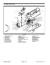
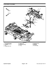
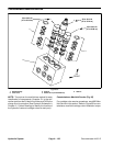
Removal (Fig. 91)
1. Park machine on a level surface, lower cutting deck,
stop engine, engage parking brake and remove key
from the ignition switch.
2. Read the General Precautions for Removing and
Installing Hydraulic System Components at the begin-
ning of this section.
3. Remove deck covers as needed to allow access to
lift cylinder hoses and fasteners.
4. To prevent contamination ofhydraulic system during
lift cylinder removal, thoroughly clean exterior of cylin-
der and fittings.
NOTE: Toease installation, label thehydraulichosesto
show their correct position on the lift cylinder.
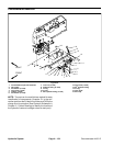
5. Disconnect hydraulic hoses from lift cylinder.
6. Remove cap screw and lock nut that secure the lift
cylinder clevis to the wing deck.
7. Remove lock nut and flat washer from the tapered
stud on the barrel end of the lift cylinder.
8. Remove lift cylinder from deck assembly.
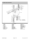
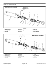
9. Remove spherical bearings from lift cylinder clevis
ends, if required.
A. On shaft clevis, remove retaining ring and then
press spherical bearing from clevis.
B. On barrel clevis, remove retaining ring and then
press tapered stud with spherical bearing and flange
nut from clevis. Remove flange nut and then spheri-
cal bearing from stud.
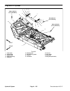
Installation (Fig. 91)
1. If removed, install spherical bearings into lift cylinder
clevis ends.
A. On shaft clevis, press spherical bearing into cle-
vis and secure with retaining ring.
B. On barrel clevis, install spherical bearing on ta-
pered stud and secure with flange nut. Torque flange
nut from 30 to 40 in--lb (41 to 54 N--m). Install stud
with spherical bearing into clevis and secure with re-
taining ring.
2. Thoroughly clean tapered surfaces of lift cylinder
stud and mounting boss on deck.
3. Position lift cylinder to cutting deck. Insert tapered
stud into deck mounting boss. Secure stud with flat
washer and lock nut. Torque flange nut from 160 to 180
ft--lb (217 to 244 N--m).
4. Insert cap screw from the front of the deck through
the deck brackets and cylinder shaft clevis. Secure cap
screw with lock nut. Torque lock nut from 160 to 180 ft--
lb (217 to 244 N--m).
5. Attach hydraulic hoses to lift cylinder.
6. Install any removed deck c overs.
7. Fill reservoir with hydraulic fluid as required.
8. After assembly is completed, operate lift cylinder to
verify that hydraulic hoses and fittings are not contacted
by anything.
Hydraulic
System