


Groundsmaster 4100--D Hydraulic SystemPage 4 -- 127
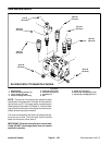
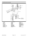
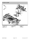
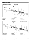
Disassembly (Fig. 89)
1. Plug all ports and clean outside of valve thoroughly.
2. Remove spool caps (item 9). Do not remove retain-
ing rings (item 12) from spools unless spool spring (item
19) is broken.
NOTE: Spools and spool bores are matched sets. Be
sure each spool is identified with the correct valve body
spool bore.
3. Remove spools (item 35) from valve body (item 36).
4. Remove bushings (item 8) and O--rings (item 11)
from spools.
5. Remove plugs (item 6).
IMPORTANT: Check location and positioning of
plungers when removing from body to assure prop-
er assembly.
6. Remove plugs (item 29), lockout springs (item 30),
poppets (item 1), s eats (item 4) and plungers (items 28
and 33).
7. Remove plug (item 17).
8. Remove detent plug (item 23), disc (item 27), detent
spring (item 21) and detent plunger (item 22).
9. Remove relief plug assembly (item 32), washers
(items 13, 14 and 15), relief valve spring (item 31) and
relief valve poppet (item 10).
10.Remove all O--rings and back--up rings from allplugs
and seats.
11.Discard all removed O--rings, back--up washers,
wiper seals and nylon poppets.
Inspection
1. Remove all nicks and burns from parts and inspect
for excessive wear.
2. Inspect all plungers and poppet seats for burrs or
roughness.
3. Inspect spool springs (item 19), relief valve spring
(item 31), lockout springs (item 30) and detent spring
(item 21) for breakage.
4. If spools (item 35) have excessive wear, the control
valve becomes non--serviceable as the spools and
spool bores are matched. Damaged spools cannot be
replaced individually.
5. Inspect relief valve poppet (item 10) for breakage or
wear.
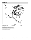
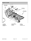
Assembly (Fig. 89)
1. Thoroughlycleanand dry all parts. Applyalightcoat-
ing of clean hydraulic oil to all control valve parts prior to
assembly.
NOTE: All O--rings, back--up washers, wiper seals and
nylon poppets should be replaced as new items.
2. Install new O--r ings (item 11) in proper grooves in
spool bores.
3. Install relief valve components (items 13, 14, 15, 31
and 10) with new O--ring (item 34) on plug assembly
(item 32).
4. Install plugs (item 6) with new back--up w ashers
(item 20) and new O--rings (item 7).
5. Install plungers (items 33 and 28).
IMPORTANT: Check location and positioning of
plungers during installation.
6. Install new O --rings (item 5) on seats (item 4). Install
new back--up washers (item 26) and O--rings (item 25)
on plugs (item 29).
7. Install seats (item 4), newpoppets (item 1) and plugs
(item 29).
8. Install plug (item 17) with new O--ring (item 18).
9. Install detent plunger (item 22), spring(item 21), disc
(item 27) and plug (item 23) with new O--r ing (item 24).
10.If retaining ring (item 12) has been removed to re-
place spool spring (item 19), install washer (item 16),
spring (item 19) and spacer (item 2) on spool. Secure
with retaining ring (item 12).
11.Slide bushings (item 8) over spools. Slide new O--
rings (item 11) over spools and position next to bush-
ings. D ip spools in clean hydraulic oil and install spool
assemblies into proper location of valve body.
12.Install spool caps (item 9) and tighten from 20 to 25
ft--lb (27 to 33 N--m).
13.Install new wiper seals (item 3).
Hydraulic
System