


Groundsmaster 4100--DPage 5 -- 32Electrical System
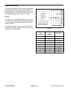
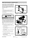
Diode Circuit Board
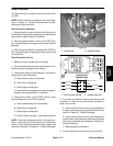
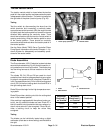
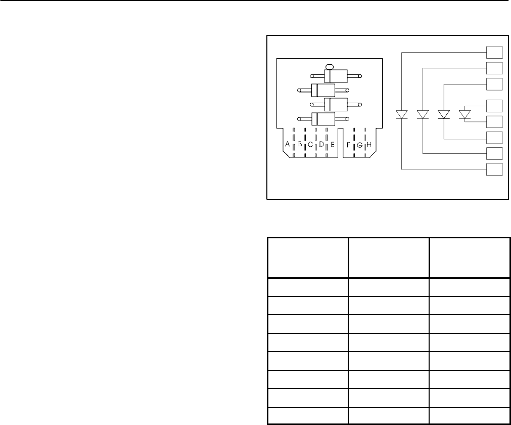
The diode circuit board (Fig. 50) contains four(4)diodes
and is located under the console housing. Diode D1--A
provides logic for the interlock system. D iodes D1--B
(right wing deck), D1-- C (frontdeck) and D1--D (left wing
deck) provide latching circuits for the PTO relay.
Testing
The diodes can be individually tested using a digital
multimeter (ohms s etting) and the table to the right. If
any of the diodes are damaged, the diode circuit board
must be replaced.
Apply dielectric grease (Toro part number 107--0342) to
circuit board contacts whenever the circuit board is
installed into the wire harness.
Figure 50
H
A
B
C
D
E
F
G
D1--A
D1--B
D1--C
D1--D
DIODE DIAGRAM
CIRCUIT BOARD
D1--D
D1--C
D1--B
D1--A
Red Lead (+)
on
Terminal
Black Lead (--)
on
Terminal
Continuity
H A YES
A H NO
G B YES
B G NO
F C YES
C F NO
E D YES
D E NO