


Groundsmaster 4100--D Page 6 -- 25 Axles, Planetaries and Brakes
7. Secure the lock nut with the stake washer.
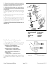
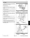
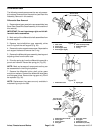
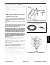
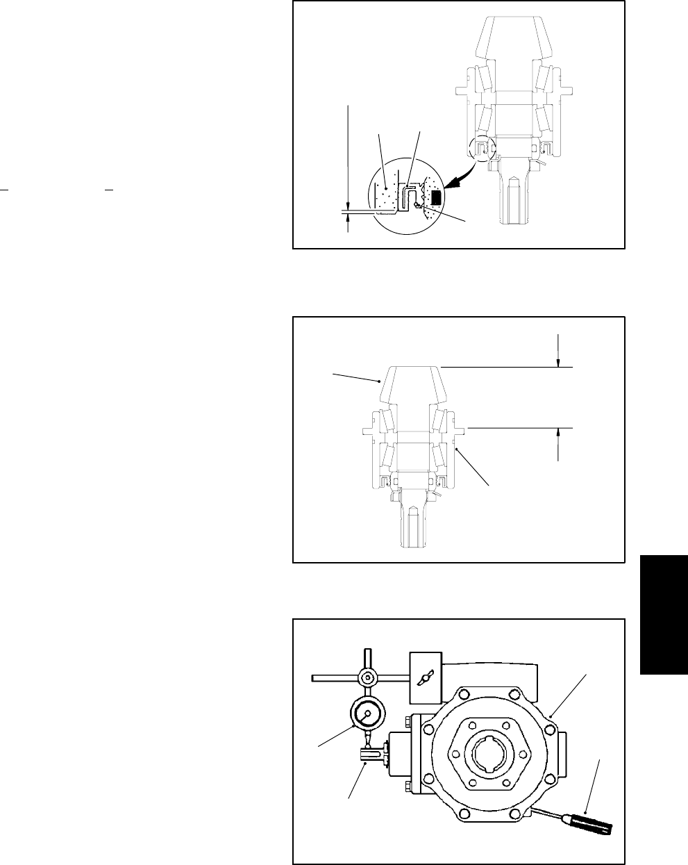
8. Use a depth gauge to measure the distance from the
end face of the input shaft/pinion gear to the mating sur-
face of the bearing case. Subtract the “Design Cone
Center Distance” from this distance to determine initial
shim thickness (Fig. 32).
DESIGN CONE CENTER DISTANCE (distance
from mating surface of axle s upport to end face of
pinion gear):
1.870 +
0.002 in. (47.5 + 0.05 mm)
NOTE: Bearing case shims are available in 0.004 in.
(0.1 mm) and 0.008 in. (0.2 mm) thickness.
9. Coat new O-rings with grease and install the bearing
case in the gear case. Place shims on the gear case and
temporarily install gear case assembly into axle case.
Tighten mounting nuts and screws from 35 to 41 ft-lb
(47to56N--m).
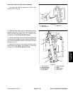
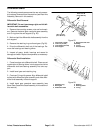
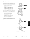
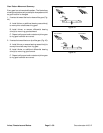
10.Insert a screwdriver through the drain plug hole to
hold ring gear and measure the pinion gear to ring gear
backlash (Fig. 33).
PINION GEAR TO RING GEAR BACKLASH:
0.004 to 0.016 in. (0.10 to 0.40 mm)
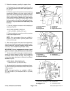
11.Adjust backlash by increasing or reducing gear case
shim thickness.
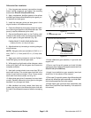
12.Check pinion gearto ring gearengagement (see Pin-
ion Gear to Ring GearEngagementin this section of this
manual).
13.Place the correct combination of shims on the gear
case. Tighten mounting nuts and screws from 35 to 41
ft-lb (47 to 56 N --m).
14.Install r etaining rings and driven gear on input shaft/
pinion gear.
15.If the drive gear (on drive motor shaft) was removed,
install the retaining rings and drive gear on the motor
shaft.
16.Use a new gasket and install the cover plate.
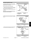
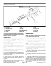
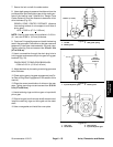
1. Oil seal
2. Bearing case
3. Seal garter spring
Figure 31
0.040 in. (1.0 mm)
1
2
3
1. Input shaft/pinion gear 2. Bearing case
Figure 32
1
2
Design
Cone Center
Distance
1. Axle case
2. Screwdriver
3. Dial indicator
4. Input shaft/pinion gear
Figure 33
1
2
3
4
Axles, Planetaries
and Brakes