


Groundsmaster 4100--D Hydraulic SystemPage 4 -- 97
CAUTION
The centering springs are under tension. Re-
move the retaining ring carefully.
10.Remove the spring retaining ring and centering
springs from the spool.
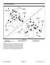
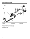
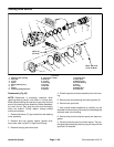
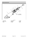
Reassembly (Fig. 65)
Check all mating surfaces. Replace any parts with
scratches or burrs that could cause leakage. Wash all
metalpartsinclean solvent. Blow themdrywithpressur-
ized air. Do not wipe parts dry with paper towels or cloth
as lint in a hydraulic system will cause damage.
NOTE: Always use new seals and O--rings when as-
sembling the steering valve.
IMPORTANT: During assembly, lubricate the new
seals with petroleum jelly. A lso, lubricate machined
surfaces and bearings with clean hydraulic fluid.
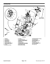
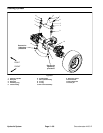
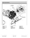
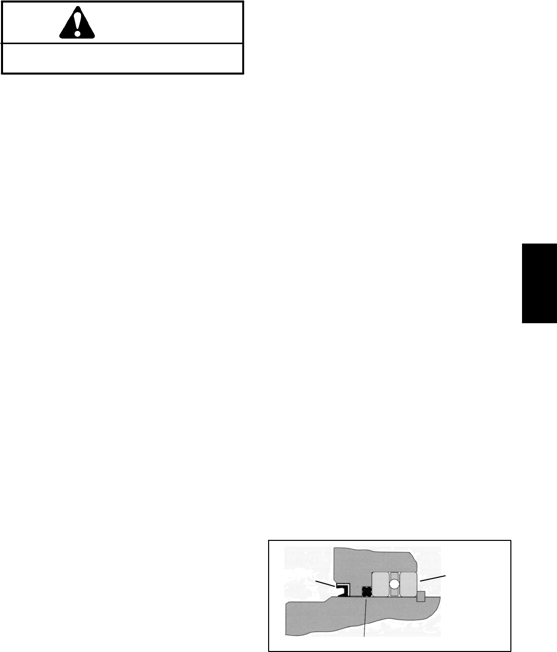
1. Install the quad seal (Fig. 66):
A. Put one of the bearing r aces and sleeve into the
housing.
B. Together, the housing and bearing race create a
groove into which the quad seal will be installed.
C. Hold the bearing race tightly against the input end
of the housing by pushing on the gerotor end of the
sleeve.
D. Fit thequadseal into its seatthroughthe input end
of the housing. Be sure the seal is not twisted.
E. Remove the sleeve and bearing race.
2. Lubricate and install the dust seal.
3. Install the centering springs in the spool. It is best to
install the two flat pieces first. Next, install the curved
pieces, three at a time.
4. Fit the retaining ring over the centering springs.
5. Apply a light coating of clean hydraulic fluid to the
spool and slide it into the sleeve. Be sure the centering
springs fit into the notches in the sleeve.
6. Install the pin.
7. Apply a light coating of petroleum jelly to the inner
edge of the dust and quad seals.
8. Put the thrust bearing and races into the housing.
The thrust bearing goes between the two races
(Fig. 66).
IMPORTANT: Do not damage the dust or quad seals
when installing the spool and sleeve assembly.
9. Apply a light coating of clean hydraulic fluid to the
spool and sleeve assembly and carefully slide the as-
sembly into the housing.
10.Clamp thehousingin avise.Use only enoughclamp-
ing force to hold the housing securely.
11.Lubricate and install a new O-ring seal in the groove
in the housing.
12.Install the wear plate and align screw holes in the
wear plate with threaded holes in the housing.
NOTE: The holes in the wear plate are symmetrical.
13.Install the geroter drive, making sure the slot in the
drive engages the pin.
14.Lubricate and install new O-ring in wear plate
groove.
15.Install the gerotor and align the screw holes.
16.Lubricate and install new O-ring in gerotor ring
groove.
17.Lubricate and install new O-ring and seal ring in ger-
otor star groove.
18.Install the spacer.
19.Install theendcap andseven(7) capscrews.Tighten
the cap screws, in a crossing pattern, from 140 to 160
in-lb (16 to 18 N--m).
20.Remove the steering valve from the vise.
21.Install the relief valve and plug. Tighten the plug to
150 in-lb (17 N--m).
Thrust Bearing
and Race (2)
Quad Seal
Dust Seal
Figure 66
Hydraulic
System