


Groundsmaster 4100--DHydraulic System Page 4 -- 108
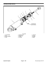
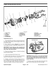
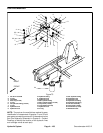
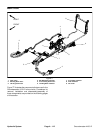
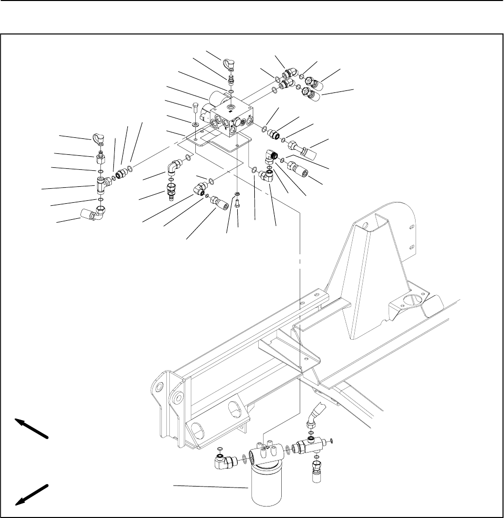
Fan Drive Manifold
1. Fan drive manifold
2. O--ring
3. Test fitting
4. Dust cap (2 used)
5. O--ring
6. 45
o
hydraulic fitting (2 used)
7. O--ring
8. Hydraulic hose
9. Hydraulic hose
10. Hydraulic fitting
11. Hydraulic hose
12. Hydraulic hose
13. 90
o
hydraulic fitting
14. 90
o
hydraulic fitting (2 used)
15. Cap screw (2 used)
16. Lock washer (2 used)
17. Hydraulic hose
18. O--ring
19. 90
o
hydraulic fitting
20. Hydraulic hose
21. Hydraulic hose
22. Hydraulic tee fitting
23. Hydraulic test fitting
24. Oil filter assembly
25. Cap screw (2 used)
26. Flat washer (2 used)
27. Manifold mount
Figure 75
7
9
1
2
3
4
8
6
5
10
5
5
5
5
7
7
7
7
7
7
10
11
12
15
16
13
14
17
18
19
20
14
21
22
23
24
25
26
4
27
FRONT
RIGHT
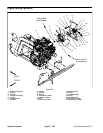
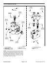
NOTE: The ports on the manifold are marked for easy
identification of components. Example: P1 and P2 are
gearpumpconnectionportsand S1is thesolenoidvalve
port (See Hydraulic Schematic in Chapter 9 -- Foldout
Drawings to identify the function of the hydraulic lines
and cartridge valves at each port).