


Groundsmaster 4100--DHydraulic System Page 4 -- 116
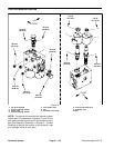
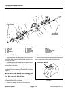
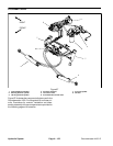
Assembly (Fig. 80)
NOTE: When assembling the motor, check the identifi-
cation marks made during disassembly to make sure
the parts are properly aligned during assembly.
1. LubricateO--rings, pressureseals, back--up gaskets
and seal grooves with a thin coat of petroleum jelly. Lu-
bricate all other internal parts freely with clean hydraulic
oil.
2. Install new shaft seal into front flange.
3. Install lubricated pressure seals into the grooves in
the front flange and rear cover. Follow by carefully plac-
ing the back-- up rings into the grooves.
4. Install new O--rings to the body.
5. Lubricate gear faces and bearing surfaces of drive
gear, idler gear and bearing blocks with clean hydraulic
oil. Carefully assemble bearing blocks and gears noting
identification marks made during disassembly.
6. Position the motor body on its side. Carefully slide
bearing block and gear assembly into the body cavity
using identification marks made during disassembly.
7. Remove any excess lubrication from mating sur-
faces of body, rear cover and front flange. Make sure
that these surfaces are clean and dry.
8. Install dowel pins in body.
IMPORTANT: Do not dislodge O--rings, pressure
seals or back--up rings during final assembly.
9. Gently slide the rear cover onto the assembly using
marker or scribe mark for proper location. Firm hand
pressure should be sufficient to engage the dowel pins.
10.Position the motor with rear cover downwards. Care-
fully slide the front flange onto the assembly using mark-
er line for proper location.
11.Install the four (4) cap screws and hand tighten.
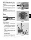
IMPORTANT: Prevent damage when clamping the
deck motor into a vise; clamp on the front flange
only. Also, use a vise with s oft jaws.
12.Place motor front flange in a vise and alternately
torque the screws from 33 to 40 ft--lb (45 to 55 N--m).
13.Put a small amount of hydraulic oil in port on motor
and rotate driveshaft one revolution. Protect the shaft if
using a pliers. If drive shaft binds, disassemble motor
and repeat assembly process.
14.Make sure that tapered surface of motor shaft and
spider hub are thoroughly clean.
15.Place woodruff key in motor shaft slot. Install spider
hub and tab washer on shaft. Secure spider hub to shaft
with nut. Torque nut from 27 to 33 ft--lb (37 to 45 N--m) .
16.Secure nut to motor shaft by bending small tab of tab
washer into keyway and large tab against nut.
17.Remove motor from vise.