


Groundsmaster 4100--DPage 6 -- 14Axles, Planetaries and Brakes
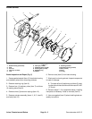
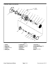
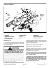
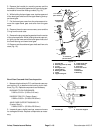
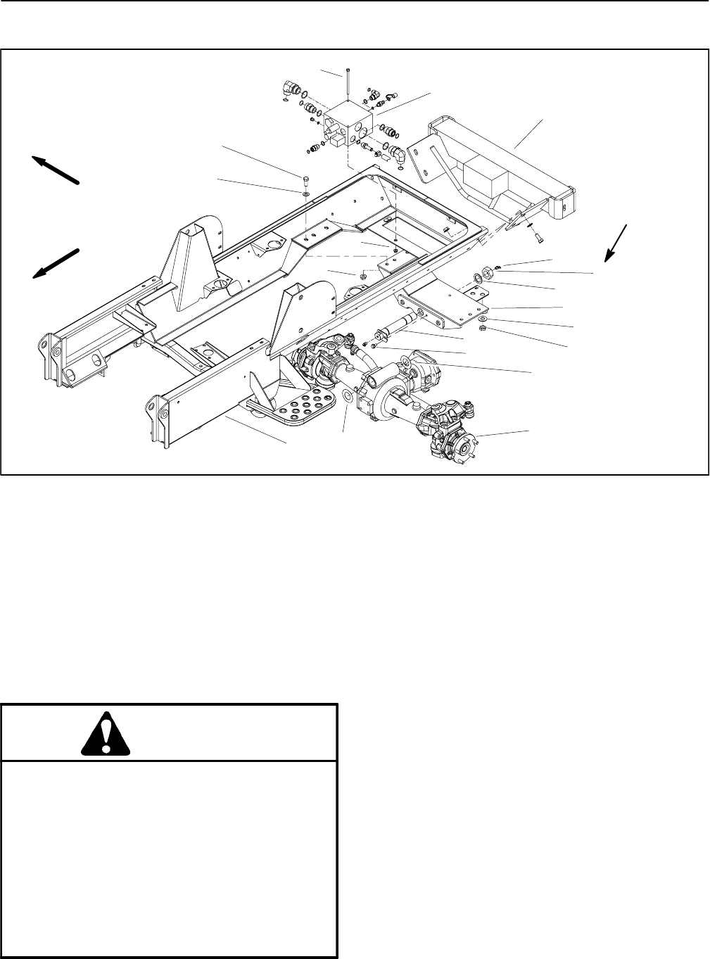
Rear Axle Assembly
1. Frame
2. Cap screw (6 used)
3. Flat washer
4. Bulkhead lock nut (2 used)
5. Washer
6. Thrust washer (thick)
7. Grease fitting (2 used)
8. Rear axle assembly
9. Thrust washer (thin)
10. Washer head screw
11. Pivot pin
12. Rear frame mount
13. Washer
14. Lock nut
15. Flange nut
16. Rear bumper
17. Hydraulic manifold (4WD)
18. Cap screw (2 used)
19. Flange nut (2 used)
Figure 10
FRONT
RIGHT
1
2
3
4
6
7
8
9
10
11
12
16
17
13
14
5
15
18
19
See text for
tightening
procedure
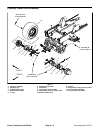
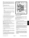
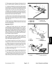
Removal (Fig. 10)
1. Park machine on a level surface, lower cutting deck,
stop engine, engage parking brake and remove key
from the ignition switch.
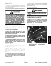
CAUTION
When changing attachments, tires or perform-
ing other service, use correct jacks and sup-
ports. Make sure machine is parked on a solid,
level surface such as a concrete floor. Prior to
raising machine, remove any attachments t hat
may interfere with the safe and proper raising of
themachine.Always chock orblockwheels. Use
jack stands to support the raised machine. If the
machine is not properly supported by jack
stands, the machine may move or fall, which
may result in personal injury.
2. Chock front wheels and jack up rear of machine (see
Jacking Instructions in Chapter 1 -- Safety). Support ma-
chine with suitable jack stands.
3. Drain oil from rear axle and axle gearbox.
4. Remove both wheels from rear axle.
5. Remove hydraulic motor from rear axle assembly
(see Rear Axle Motor in the Service andRepairssection
of Chapter 4 -- Hydraulic System).
6. Remove steering cylinder from rear axle (see Steer-
ing Cylinder in theService and Repairs section of Chap-
ter 4 -- Hydraulic System).
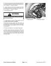
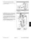
7. Disconnect both steering cylinder hydraulic hoses
from hydraulic tubes at rear frame mount (Fig. 11). Re-
move bulkhead locknuts andwashersthatsecure steer-
ing cylinder hydraulic tubes to rear frame mount.
Separate tubes from frame mount.