


Groundsmaster 4100--DHydraulic System Page 4 -- 96
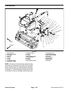
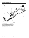
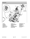
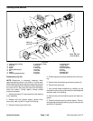
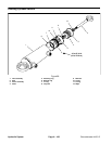
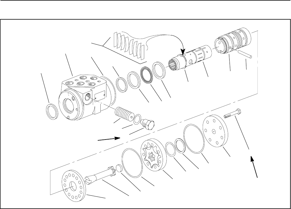
Steering Valve Service
1. Steering valve housing
2. Dust seal
3. O--ring
4. Spool
5. Spring retaining ring
6. Pin
7. Sleeve
8. Centering springs/spacers
9. Cap screw (7 used)
10. End cap
11. O--ring
12. Seal ring
13. O--ring
14. Geroter
15. O--ring
16. Spacer
17. Geroter drive
18. Wear plate
19. Bearing race
20. Thrust bearing
21. Plug
22. O--ring
23. Relief valve
24. Quad seal
Figure 65
3
5
6
9
10
16
11
12
13
14
15
4
7
1
2
17
18
19
19
20
21
22
23
24
8
140 to 160 in--lb
(16to18N--m)
150 in--lb
(17 N--m)
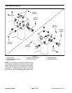
Disassembly (Fig. 65)
NOTE: Cleanliness is extremely important when
repairing steering control units. Work in a clean area.
Before disconnecting the hydraulic lines, clean the port
area of the steering valve assembly. Before disassem-
bly, drain the oil, then plug the ports and thoroughly
clean the exterior. During repairs, always protect
machined surfaces.
1. Remove the seven (7) cap screws from the steering
valve assembly.
2. Remove end cap, geroter, spacer, geroter drive,
wear plate, seal ring and O--rings from housing.
3. Remove the plug and relief valve.
4. Slide the spool and sleeve assembly from the hous-
ing.
5. Remove the thrust bearing and bearing races (2).
6. Remove the quad seal.
7. Use a small blade screwdriver to carefully pry the
dust seal fromthehousing.Becareful to not damagethe
dust seal seat in the housing.
8. Remove the pin that holds the spool and sleeve to-
gether.
9. Carefully slide the spool out of the sleeve. The cen-
tering springs and spring retaining ring will stay with the
spool as it is removed.