


Groundsmaster 4100--DCutting Deck
Page 8 -- 16
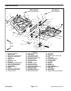
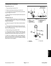
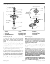
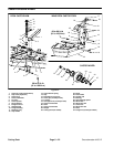
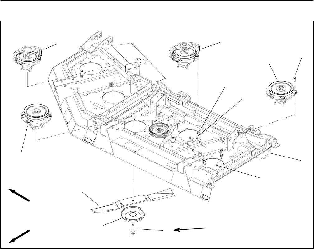
Blade Spindle
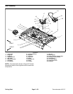
1. Cutting deck
2. Drive spindle: single pulley (2 used)
3. Low driven spindle (3 used)
4. Drive spindle: double pulley (1 used)
5. Flange head screw
6. Flange nut
7. Blade bolt
8. Cutting blade (7 used)
9. Anti--scalp cup
10. High driven spindle (1 used)
11. Flat washer
12. Cap screw
Figure 13
4
3
1
10
11
12
88 to 108 ft--lb
(119 to 146 N--m)
2
FRONT
RIGHT
5
7
6
9
8
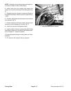
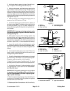
Removal (Fig. 13)
1. Park machine on a level surface, lower cutting deck,
stop engine, engage parking brake and remove key
from the ignition switch.
2. If drive spindle is to be serviced, remove hydraulic
motor from cutting deck (see Cutting Deck Motor Re-
moval in the Service and Repairs Section of Chapter 4
-- Hydraulic System). Position motor away from spindle.
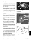
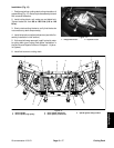
3. Remove belt covers from top of cutting deck. Loosen
idler pulley to release belt tension (see Idler Assembly
Removalinthis section).R emove drive beltfrom spindle
to be serviced.
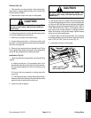
4. Start the engine and raise the cutting deck. Stop en-
gine and remove key from the ignition switch. Latch or
block up the cutting deck so it cannot fall accidentally.
5. Remove cutting blade, anti--scalp cup and blade bolt
from spindle to be serviced.
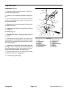
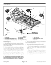
6. Remove spindle housing assembly from deck:
A. For driven spindle assemblies, remove eight (8)
flange head screws with flange nuts that secure
spindle to deck.
B. Fordrivespindleassemblies,loosen andremove
four (4) flange head screws with flange nuts that se-
cure spindle to deck. Then, remove four (4) cap
screws with flatwashersthatsecurespindle and mo-
tor mount to deck.