


Groundsmaster 4100--D Hydraulic SystemPage 4 -- 41
Procedure for Traction Circuit Reducing Valve (PR)
Pressure Test
1. Make sure hydraulic oil is at normal operating tem-
perature by operating the machine for approximately 10
minutes. Make sure the hydraulic tank is full.
2. Parkmachineon a level surface with thecuttingdeck
lowered and off. Make sure engine is off and the parking
brake is engaged.
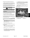
CAUTION
Prevent personal injury and/or damage to equip-
ment. Read all WARNINGS, CAUTIONS and Pre-
cautions for Hydraulic Testing at the beginning
of this section.
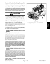
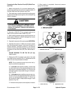
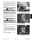
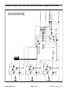
3. Connect a 1000 PSI (70 bar) gauge to test port on
4WD control manifold under radiator (Fig. 29).
4. After installing pressure gauge, start engine and run
at idle speed. Check for hydraulic leakage and correct
before proceeding with test.
5. Operatetheengine at full engine speed(2870RPM).
Makesurethat transport/4WDswitchis in the4WDposi-
tion.
6. Siton seat, apply brakes fully and slowlydepress the
traction pedal in the reverse direction. While pushing
traction pedal, look at pressure reading on gauge:
GAUGE READING TO BE 650 PSI (45 bar)
(approximate).
7. Stop engine and record test results.
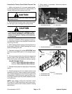
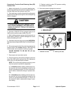
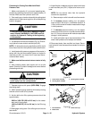
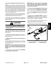
8. Pressure reducing valve (PR) is located on the front
side of the 4WD control manifold (Fig. 30). Adjustment
of this valve can be performed as follows:
NOTE: Do not remove the pressure reducing valve
from the hydraulic manifold for adjustment.
A. To increase pressure setting, remove cap on re-
ducing valve and turn the adjustment socket on the
valveinaclockwisedirection.A1/8turnonthesock-
et will make a measurable change in pressure set-
ting.
B. To decrease pressuresetting,remove cap on re-
ducing valve and turn the adjustment socket on the
valve in a counterclockwise direction. A 1/8 turn on
the socket will make a measurable change in pres-
sure setting.
C. Recheck reducing valve (PR) pressure setting
and readjust as needed.
9. Disconnect pressure gauge from test port.
1. 4WD control manifold
2. Pressure test port
Figure 29
2
1
1. Manifold: front side 2. Reducing valve (PR)
Figure 30
1
2
Hydraulic
System