Groundsmaster 4100--DPage 5 -- 12Electrical System
Fuses
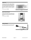
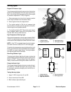
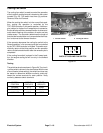
The fuse blocks arelocated under the operator’s control
console.
Identification, Function and Wiring
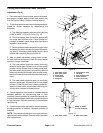
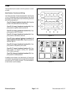
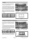
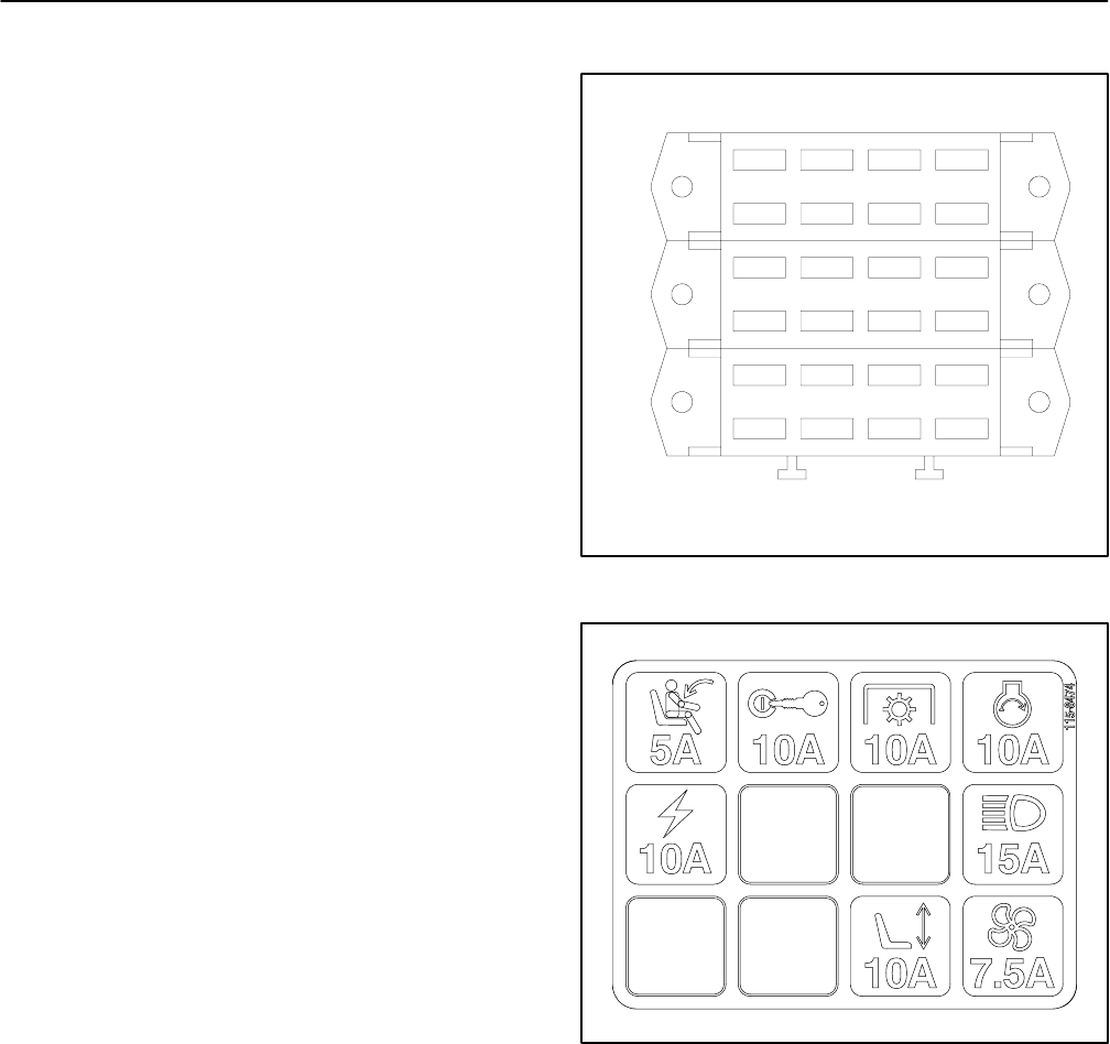
The fuses are held in three (3) fuse blocks. Use Figures
13 and 14 to identify each individual fuse and its correct
amperage. Each fuse holder has the following functions
and wire connected to it.
FuseF1(5amp)(fuseblocklocation A1): Supplies
power to the seat switch and seat relay.
Fuse F2 (10 amp) (fuseblock location A2): Sup-
plies power to ignition switch terminal B.
Fuse F3 (10 amp) (fuseblock location A3): Sup-
plies power to the PTO switch.
Fuse F4 (10 amp) (fuseblock location A4): Sup-
plies power to the starter solenoid.
Fuse F5 (when optional lighting is installed) (15
amp) (fuseblock location B4): Supplies power for
optional light kit.
Fuse F8 (10 amp) (fuseblock location B1): Sup-
plies power to the power point outlet.
Fuse F9 (7.5 amp) (fuseblock location C4): Sup-
plies power for engine cooling fan operation
(TEC--5002 controller).
Fuse F10 (10 amp) (fuseblock location C3): Sup-
plies power for seat operation.
In addition to the fuses in the fuse blocks, a 2 amp fuse
is included in the wire harness to protect the logic power
circuit for the TEC--5002 controller. This fuse resides in
a fuse holder near the battery.
Figure 13
A
B
1234
C
10A5A
10A
10A
10A
OPT
15A
10A
7.5A
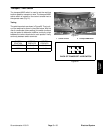
Figure 14


