


Groundsmaster 4100--D Page 5 -- 21 Electrical System
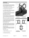
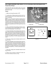
Start, Engine Shutdown, Seat, Alarm, PTO, PTO Overtemp, Down Latching and Over
Temperature Relays
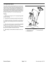
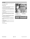
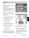
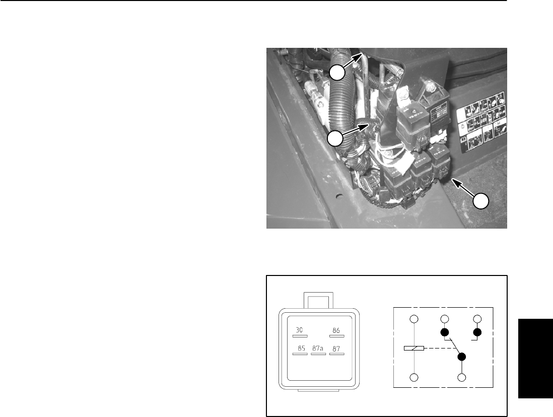
These eight (8) relays are located under the console
housing cover (Fig. 30). The wiring harness is tagged to
identify each relay.
Testing
1. Make sure that ignition switch is OFF.
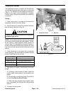
2. Locate relay and disconnect the machine wire har-
ness connector from the relay. Remove relay from ma-
chine if necessary.
NOTE: Prior to taking small resistance readings with a
digital multimeter, short the meter test leads together.
The meter will display a small resistance value (usually
0.5 ohms or less). This resistance is due to the internal
resistance of the meter and test leads. Subtract this val-
ue from the measured value of the component you are
testing.
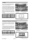
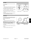
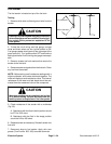
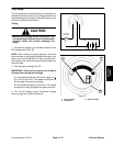
3. Using a multimeter (ohms setting), measure coil re-
sistance between terminals 85 and 86 (Fig. 31). Resist-
ance should be between 70 and 90 ohms.
4. Connectmultimeter (ohms setting) leads to relay ter-
minals 30 and 87. Ground terminal 86 and apply +12
VDCtoterminal 85.Therelay should havecontinuitybe-
tween terminals 30 and 87 as +12 VDC is applied to ter-
minal 85. The relay should not have continuity between
terminals 30 and 87 as +12 VDC is removed from termi-
nal 85.
5. Disconnect voltage and multimeter leads from the
relay terminals.
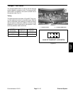
6. Connectmultimeter (ohms setting) leads to relay ter-
minals 30 and 87A. Ground terminal 86 and apply +12
VDC toterminal85. The relay should not havecontinuity
between terminals 30 and 87A as +12 VDC is applied to
terminal 85. The relay should have continuity between
terminals 30 and 87A as +12 VDC is removed from ter-
minal 85.
7. Disconnect voltage and multimeter leads from the
relay terminals.
8. Secure relay to machine if removed. Connect ma-
chine wire harness connector to relay.
1. Control panel 2. Relay location
Figure 30
1
2
2
Figure 31
86
85
87A 87
30
Electrical
System