


Groundsmaster 4100--D Hydraulic SystemPage 4 -- 15
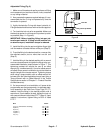
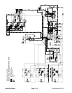
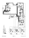
Lower Cutting Deck
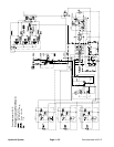
A four section gear pump is coupled to the piston (trac-
tion) pump. The third gear pump section supplies hy-
draulic flow to both the lift/lower control valve and the
steering control valve. Hydraulic flow from this pump
section is delivered to the steering and lift/lower circuits
through a proportional flow divider that is located in the
fan drive manifold. This pump section takes its suction
from the hydraulic reservoir.
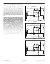
When the cutting deck is in a stationary position, flow
from the gear pump is by--passed through the lift/lower
control valve, counterbalance manifold, oil filter and
traction charge circuit.
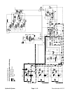
To lower the cutting deck, the center lift lever on the lift/
lower control valve is pushed to allow valve shift in the
lift/lowercontrol.This valvechangeallows apassagefor
oil flow from the rod end of the front deck lift cylinders.
The weight of the cutting deck causes the lift cylinders
to extend, and lower the cutting deck. Oil from the rod
end of the cylinders is allowed to return to the traction
charge circuit. When the lift lever is released, the lift cyl-
inders and cutting deck is held in position.
The drop speed of the front cutting deck is regulated by
an adjustable flow control valve that is located in the hy-
draulic lines between the lift/lower control valve and the
deck lift cylinders.
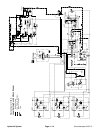
To lower a wing deck, the appropriate lift lever on the lift/
lower control valve is pushed to allow valve shift in the
lift/lower control valve. This valve change causes a
valve shift in the counterbalance manifold and oil flow to
the barrel end of the lift cylinder. Higher hydraulic pres-
sure against the barrel end of the cylinder causes the
cylinder shaft to extend, and lower the wing deck. Oil
from the piston end of the cylinder returns to the traction
charge circuit. When the lift lever is released, the lift cyl-
inder and wing deck is held in position.
An adjustablecounterbalancevalve (CB) in thecounter-
balance manifold maintains back pressure on the deck
lift cylinders to allow some of the cutting deck weight to
be transferred to the traction unit to improve traction. A
relief valve located in the lift/lowercontrol valve limits lift/
lower circuit pressure to 1500 PSI (103 bar). Excess cir-
cuit flow is routed to the oil filter and then to the traction
charge circuit.
Hydraulic
System