


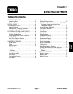
Groundsmaster 4100--DPage 5 -- 8Electrical System
Electrical System Quick Checks
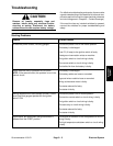
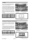
Battery Test (Open Circuit Test)
Use a multimeter to measure the voltage between the
battery terminals.
Set multimeter to the DC volts setting. The battery
should be at a temperature of 60
o
F to 100
o
F(16
o
Cto
38
o
C). The ignition key should be offand all accessories
turned off. Connect the positive (+) meter lead to the
positive battery post and the negative (--) meter lead to
the negative battery post.
NOTE: Thistestprovidesarelative condition of the bat-
tery. Load testing of the battery will provide additional
and more accurate information.
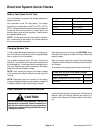
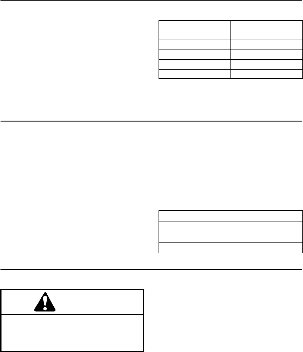
Voltage Measured
Battery Charge Level
12.68 V (or higher) Fully charged (100%)
12.45 V 75% charged
12.24 V 50% charged
12.06 V 25% charged
11.89 V 0% charged
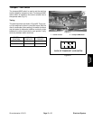
Charging System Test
This is a simple test used to determine if a charging sys-
tem is functioning. It will tell you if the charging system
has an output, but not its capacity.
Use a digital multimeter set to DC volts. Connect the
positive (+) multimeter lead to the positive battery post
and the negative (--) multimeterlead to the negativebat-
tery post. Keep the test leads connected to the battery
posts and record the battery voltage.
NOTE: Upon starting the engine, the battery voltage
will drop and then should increase once the engine is
running.
NOTE: Depending upon the condition of the battery
charge and battery temperature, the battery voltage will
increase at different rates as the battery charges.
Start the engine and run at high idle (2870 RPM). Allow
the battery to charge for at least 3 minutes. Record the
battery voltage.
After r unning the engine for at least 3 minutes, battery
voltageshouldbe atleast0.50 volthigher than initialbat-
tery voltage.
An example of a charging system that is functioning:
At least 0.50 volt over initial battery voltage.
Initial Battery Voltage = 12.30 v
Battery Voltage after 3 Minute Charge = 12.85 v
Difference = +0.55 v
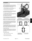
Check Operation of Interlock Switches
CAUTION
Do not disconnect safety switches. They are for
the operator’s protection. Checkthe operationof
the interlock switches dailyfor proper operation.
Replace any malfunctioning switches before op-
erating the machine.
Interlock s witch operation is described in the Operator’s
Manual. Testing of interlock switches and relays is in-
cluded in the Component Testing section of this Chap-
ter.