


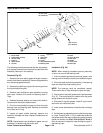
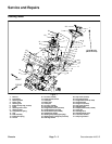
Groundsmaster 4100--DPage 6 -- 28Axles, Planetaries and Brakes
Differential Gear Installation
1. If the ring gear was removed, use medium strength
thread locking compound and tighten the mounting
screws from 22 to 25 ft-lb (30 to 34 N --m).
2. Apply molybdenum disulfide grease to the splines
andbearingsurfaces of thedifferential piniongears,pin-
ion washers and side gears.
3. Install the side gear shims and side gears in their
original location in the differential case.
4. Place the differential pinion gears and pinion wash-
ers in their original location in the differential case. Tem-
porarily install the differential pinion shaft.
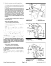
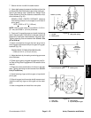
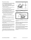
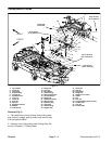
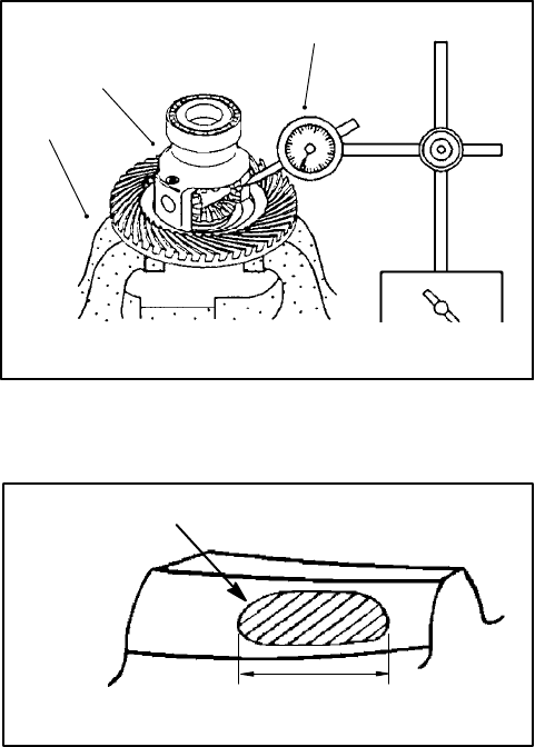
5. Secure the differential case in a vise. Position a dial
indicator at the tooths center and measure the differen-
tial pinion gear to side gear backlash (Fig. 39).
PINION GEAR TO SIDE GEAR BACKLASH:
0.004 to 0.016 in. (0.10 to 0.40 mm)
6. Adjust backlash by increasing or reducing side gear
shim thickness.
NOTE: Side gear shims are available in 0.043 in. (1.1
mm), 0.047 in. (1.2 mm) and 0.051 in. (1.3 mm) thick-
ness.
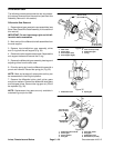
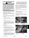
7. Apply gear marking c ompound, such as DyKemR
Steel Blue lightly over several gear teeth.
8. While applying a light load to either side gear, rotate
either pinion gear until the side gears have made one
complete revolution.
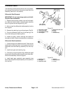
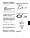
9. Ideal tooth contact should cover more than 35% of
each tooth surface. The contact area should be in the
center of each tooth and extend 1/3 to 1/2 way across
each tooth from the toe (small) end (Fig. 40).
10.Adjust side gear shims if necessary to correct tooth
contact. Recheck differential pinion gear to side gear
backlash if any changes are made.
11.After backlash and tooth contact have been ad-
justed, align the hole in the differential p inion shaft with
the hole in the differential case and install a new spring
pin.
1. Vise
2. Differential gear case
3. Dial indicator
Figure 39
1
2
3
Figure 40
More than 35% total tooth contact
1/3 to 1/2 of entire width
from small end of tooth
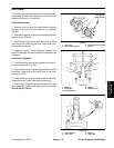
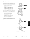
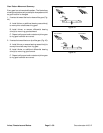
12.Install differential gear assembly in right side axle
support half.
13.Coat a new O-ring with grease and install left side
axlesupport half.Tightenaxle supportcase screwsfrom
35 to 41 ft-lb (47 to 56 N--m).
14.Install input shaft/pinion gear assembly (see Input
shaft/Pinion in this section of this manual).
15.Coat new O-rings with grease, align differential shaft
splines with differential gear assembly and slide differ-
ential shaft assemblies onto axle support.
16.Install bevel gear case/axle case assemblies (see
Bevel Gear Case/Axle Case Assembly in this section of
this manual).