


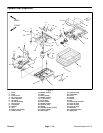
Groundsmaster 4100--D Page 7 -- 5 Chassis
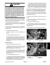
CAUTION
When changing attachments, tires or perform-
ing other service, use correct jacks and sup-
ports. Make sure machine is parked on a solid,
level surface such as a concrete floor. Prior to
raising machine, remove any attachments t hat
may interfere with the safe and proper raising of
themachine.Always chock orblockwheels. Use
jack stands to support the raised machine. If the
machine is not properly supported by jack
stands, the machine may move or fall, which
may result in personal injury.
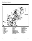
3. Chock rear wheels and jack up front of machine.
Support machine on jack stands. Remove front wheel
next to lift arm that is being removed.
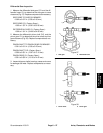
4. Remove flange head screw and lock nut that secure
lift cylinder pin to lift arm. Remove pin and separate lift
cylinder from lift arm.
5. Remove lock nut that secures lift arm pin. Support lift
arm and slide pin from frame and lift arm. Remove lift
armfromframe.
6. As needed, disassemble lift arm:
A. Remove height--of--cut chain and damper as-
sembly.
B. Press flange bearings from lift arm.
C. Remove flange nut, flat washer and support hub
fromtaperedstud.Remove tapered stud withspheri-
cal bearing from lift arm after removing retaining ring
from lift arm. R emove flange nut and spherical bear-
ing from stud.
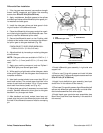
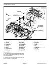
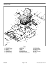
Installation (Fig. 2)
1. If removed, install components to lift arm.
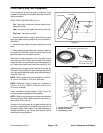
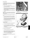
A. Assemble height--of--cut chain u--bolt so that
threaded portion of u--bolt extends 0.750” (19.1 mm)
above mounting plate on lift arm (Fig. 3).
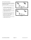
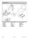
B. If rod ends were removed from damper, apply
Loctite #242 to threads and install on damper. Install
damper assembly to lift arm with damper rod end to-
ward deck (Fig. 4).
C. Press flange bearings into lift arm.
D. Install spherical bearing on tapered stud and se-
cure with flange nut. Torque flange nut from 30 to 40
ft--lb (41 to 54 N--m). Install studwith sphericalbear-
ing into lift arm and secure with retaining ring.
E. Thoroughly clean tapered surfaces of stud and
mounting boss of support hub. Secure support hub
(position slotted hole in hub toward rear of deck) to
tapered stud with flat washer and flange nut. Tighten
flange nut from 155 to 185 ft-- lb (211 to 251 N--m) .
2. Position lift arm to frame and insert lift arm pin. En-
gage roll pin into frame slots and install lock nut on pin.
Torque lock nut from 60 to 70 ft--lb (81 to 94 N--m).
3. Align lift cylinder with lift arm. Slide lift cylinder pin
through lift arm and cylinder end. Secure pin with flange
head screw and lock nut.
4. Install front wheel assembly. Lower machine to the
ground.
5. Install cutting deck (see Cutting Deck Installation in
Chapter 8 -- Cutting Deck).
6. Lubricate lift arm grease fittings.
7. Afterassemblyis completed, raise and lower thecut-
ting deck toverifythathydraulic hoses and fittings donot
contact anything.
8. Check height--of--cut and deck pitch adjustment.
1. Lift arm 2. U--bolt threads
Figure 3
0.750”
(19.1 mm)
1
2
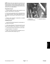
1. Lift arm
2. Deck castor arm
3. Support hub
4. Damper
Figure 4
1
2
3
4
Chassis