


Groundsmaster 4100--D Hydraulic SystemPage 4 -- 125
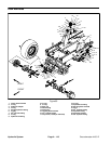
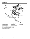
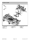
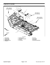
Removal (Fig. 88)
1. Park machine on a level surface, lower cutting deck,
stop engine, engage parking brake and remove key
from the ignition switch.
2. Read the General Precautions for Removing and
Installing Hydraulic System Components at the begin-
ning of this section.
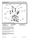
3. To prevent contamination ofhydraulic system during
control valve removal, thoroughly clean exterior of con-
trol valve and fittings.
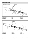
4. Remove lift/lower control valve using Figure 88 as a
guide.
5. If hydraulic fittings are to be removed from control
valve, mark fitting orientation to allow correct assembly.
Remove fittings from valve and discard O--rings.
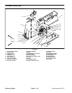
Installation (Fig. 88)
1. If fittings were removed from control valve, lubricate
and place new O--rings onto fittings. Install fittings into
port openings using marks made during the removal
process to properly orientate fittings. Tighten fittings
(see Hydraulic Fitting Installation in the General Infor-
mation section of this chapter).
2. Install lift/lower control valve using Figure 8 8 as a
guide.
A. Ifvalve bracket(item2) was removed, tightencap
screw(item24)onlyuntil thew asher (item23)begins
to seat against the isolator (item 3). The isolator
should not be deformed.
3. After installation, check operation of c utting deck
raise and lower switches (see Cutting Deck Raise and
Lower Switches in the Adjustment section of C hapter 5
-- Electrical System).
4. Make surehydraulic tank is full. Add correctoil ifnec-
essary before returning machine to service.
Hydraulic
System